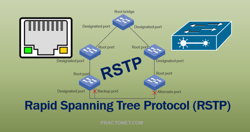
To further alleviate the 30 to 50 second convergence delays with STP, enhancements were made to the original IEEE 802.1D standard. The result was 802.1w, or Rapid Spanning Tree Protocol (RSTP RSTP is similar in many respects to STP. BPDU’s are forwarded between switches, and a Root Bridge is elected, based on the lowest Bridge ID. Root Ports and Designated Ports are also elected. RSTP defines five port types:
- Root Port – Switch port on each switch that has the best Path Cost to the Root Bridge (same as STP).
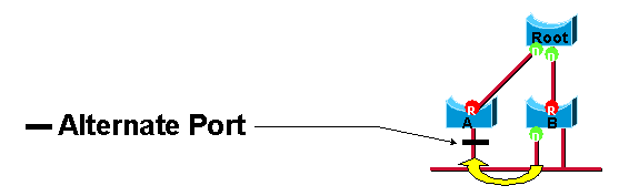
- Alternate Port – A backup Root Port, that has a less desirable Path Cost. An Alternate Port is placed in a discarding state.
- Designated Port – Non-Root port that represents the best Path Cost for each network segment to the Root Bridge (same as STP). Designated ports are also referred to as Point-to-Point ports.
- Backup Port – A backup Designated Port, that has a less desirable Path Cost. A Backup Port is placed in a discarding state.
- Edge Port – A port connecting a host device, which is moved to a Forwarding state immediately. If an Edge Port receives a BPDU, it will lose its Edge Port status and participate in RSTP calculations. On Cisco Catalyst switches, any port configured with PortFast becomes an Edge Port.
The key benefit of RSTP is speedier convergence. Switches no longer require artificial Forwarding Delay timers to ensure a loop-free environment. Switches instead perform a handshake synchronization to ensure a consistent topology table. During initial convergence, the Root Bridge and its directly-connected switches will place their interfaces in a discarding state. The Root Bridge and those switches will exchange BPDU’s, synchronize their topology tables, and then place their interfaces in a forwarding state. Each switch will then perform the same handshaking process with their downstream neighbors. The result is convergence that completes in a few seconds, as opposed to 30 to 50 seconds.
Port States
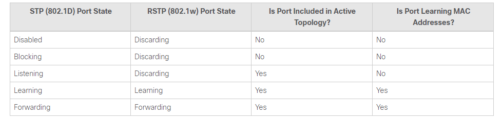
There are only three port states left in RSTP that correspond to the three possible operational states. The 802.1D disabled, blocking, and listening states are merged into a unique 802.1w discarding state.
Port Roles
The role is now a variable assigned to a given port. The root port and designated port roles remain, while the blocking port role is split into the backup and alternate port roles. The Spanning Tree Algorithm (STA) determines the role of a port based on Bridge Protocol Data Units (BPDUs). In order to simplify matters, the thing to remember about a BPDU is there is always a method to compare any two of them and decide whether one is more useful than the other. This is based on the value stored in the BPDU and occasionally on the port on which they are received.
Root Port Roles
The port that receives the best BPDU on a bridge is the root port. This is the port that is the closest to the root bridge in terms of path cost. The STA elects a single root bridge in the whole bridged network (per-VLAN). The root bridge sends BPDUs that are more useful than the ones any other bridge sends. The root bridge is the only bridge in the network that does not have a root port. All other bridges receive BPDUs on at least one port.

Designated Port Role
A port is designated if it can send the best BPDU on the segment to which it is connected. 802.1D bridges link together different segments, such as Ethernet segments, to create a bridged domain. On a given segment, there can only be one path toward the root bridge. If there are two, there is a bridging loop in the network. All bridges connected to a given segment listen to the BPDUs of each and agree on the bridge that sends the best BPDU as the designated bridge for the segment. The port on that bridge that corresponds is the designated port for that segment.
Alternate and Backup Port Roles
These two port roles correspond to the blocking state of 802.1D. A blocked port is defined as not being the designated or root port. A blocked port receives a more useful BPDU than the one it sends out on its segment. Remember that a port absolutely needs to receive BPDUs in order to stay blocked. RSTP introduces these two roles for this purpose.
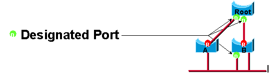
An alternate port receives more useful BPDUs from another bridge and is a port blocked. This is shown in this diagram:
A backup port receives more useful BPDUs from the same bridge it is on and is a port blocked. This is shown in this diagram:
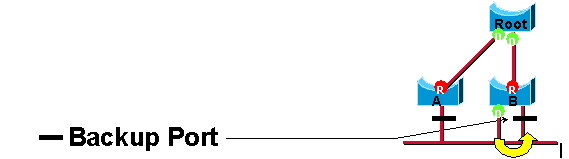
This distinction is already made internally within 802.1D. This is essentially how Cisco UplinkFast functions. The rationale is that an alternate port provides an alternate path to the root bridge and therefore can replace the root port if it fails. Of course, a backup port provides redundant connectivity to the same segment and cannot guarantee an alternate connectivity to the root bridge. Therefore, it is excluded from the uplink group.
As a result, RSTP calculates the final topology for the spanning tree that uses the same criteria as 802.1D. There is absolutely no change in the way the different bridge and port priorities are used. The name blocking is used for the discarding state in Cisco implementation. CatOS releases 7.1 and later still display the listening and learning states. This gives even more information about a port than the IEEE standard requires. However, the new feature is now there is a difference between the role the protocol determines for a port and its current state. For example, it is now perfectly valid for a port to be designated and blocking at the same time. While this typically occurs for very short periods of time, it simply means that this port is in a transitory state towards the designated forwarding state.
BPDU Format
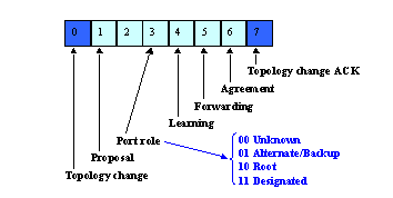
Few changes have been introduced by RSTP to the BPDU format. Only two flags, Topology Change (TC) and TC Acknowledgment (TCA), are defined in 802.1D. However, RSTP now uses all six bits of the flag byte that remain in order to perform:
Encode the role and state of the port that originates the BPDU, Handle the proposal/agreement mechanism.
BPDU Handling
BPDU are Sent Every Hello-Time
BPDU are sent every hello-time, and not simply relayed anymore. With 802.1D, a non-root bridge only generates BPDUs when it receives one on the root port. In fact, a bridge relays BPDUs more than it actually generates them. This is not the case with 802.1w. A bridge now sends a BPDU with its current information every seconds (2 by default), even if it does not receive any from the root bridge.
Faster Aging of Information
On a given port, if hellos are not received three consecutive times, protocol information can be immediately aged out (or if max_age expires). Because of the previously mentioned protocol modification, BPDUs are now used as a keep-alive mechanism between bridges. A bridge considers that it loses connectivity to its direct neighbor root or designated bridge if it misses three BPDUs in a row. This fast aging of the information allows quick failure detection. If a bridge fails to receive BPDUs from a neighbor, it is certain that the connection to that neighbor is lost. This is opposed to 802.1D where the problem might have been anywhere on the path to the root.
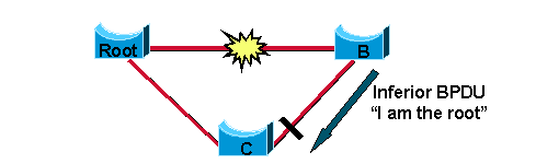
Accepts Inferior BPDUs
This concept is what makes up the core of the BackboneFast engine. The IEEE 802.1w committee decided to incorporate a similar mechanism into RSTP. When a bridge receives inferior information from its designated or root bridge, it immediately accepts it and replaces the one previously stored. Because Bridge C still knows the root is alive and well, it immediately sends a BPDU to Bridge B that contains information about the root bridge. As a result, Bridge B does not send its own BPDUs and accepts the port that leads to Bridge C as the new root port.
Rapid Transition to Forwarding State
Rapid transition is the most important feature introduced by 802.1w. The legacy STA passively waited for the network to converge before it turned a port into the forwarding state. The achievement of faster convergence was a matter of tuning the conservative default parameters (forward delay and max_age timers) and often put the stability of the network at stake. The new rapid STP is able to actively confirm that a port can safely transition to the forwarding state without having to rely on any timer configuration. There is now a real feedback mechanism that takes place between RSTP-compliant bridges. In order to achieve fast convergence on a port, the protocol relies upon two new variables: edge ports and link type.
Edge Ports
The edge port concept is already well known to Cisco spanning tree users, as it basically corresponds to the PortFast feature. All ports directly connected to end stations cannot create bridging loops in the network. Therefore, the edge port directly transitions to the forwarding state, and skips the listening and learning stages. Neither edge ports or PortFast enabled ports generate topology changes when the link toggles. An edge port that receives a BPDU immediately loses edge port status and becomes a normal spanning tree port. At this point, there is a user-configured value and an operational value for the edge port state. The Cisco implementation maintains that the PortFast keyword be used for edge port configuration. This makes the transition to RSTP simpler.
Link Type
RSTP can only achieve rapid transition to the forwarding state on edge ports and on point-to-point links. The link type is automatically derived from the duplex mode of a port. A port that operates in full-duplex is assumed to be point-to-point, while a half-duplex port is considered as a shared port by default. This automatic link type setting can be overridden by explicit configuration. In switched networks today, most links operate in full-duplex mode and are treated as point-to-point links by RSTP. This makes them candidates for rapid transition to the forwarding state.
Convergence with RSTP
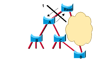
Both ports on the link between A and the root are put in designated blocking as soon as they come up. Thus far, everything behaves as in a pure 802.1D environment. However, at this stage, a negotiation takes place between Switch A and the root. As soon as A receives the BPDU of the root, it blocks the non-edge designated ports. This operation is called sync. Once this is done, Bridge A explicitly authorizes the root bridge to put its port in the forwarding state. This diagram illustrates the result of this process on the network. The link between Switch A and the root bridge is blocked, and both bridges exchange BPDUs.
Once Switch A blocks its non-edge designated ports, the link between Switch A and the root is put in the forwarding state and you reach the situation:
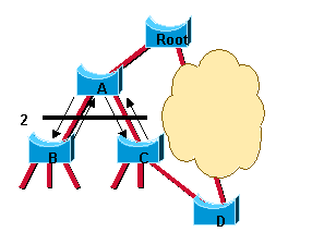
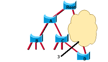
There still cannot be a loop. Instead of blocking above Switch A, the network now blocks below Switch A. However, the potential bridging loop is cut at a different location. This cut travels down the tree along with the new BPDUs originated by the root through Switch A. At this stage, the newly blocked ports on Switch A also negotiate a quick transition to the forwarding state with their neighbor ports on Switch B and Switch C that both initiate a sync operation. Other than the root port towards A, Switch B only has edge designated ports. Therefore, it has no port to block in order to authorize Switch A to go to the forwarding state. Similarly, Switch C only has to block its designated port to D. The state shown in this diagram is now reached:
The only new mechanism introduced by RSTP is the acknowledgment that a switch can send on its new root port in order to authorize immediate transition to the forwarding state, and bypasses the twice-the-forward-delay long listening and learning stages. The administrator only needs to remember these to benefit from fast convergence:
This negotiation between bridges is only possible when bridges are connected by point-to-point links (that is, full-duplex links unless explicit port configuration).
Edge ports play an even more important role now that PortFast is enabled on ports in 802.1D. For instance, if the network administrator fails to properly configure the edge ports on B, their connectivity is impacted by the link between A and the root that comes up.
UplinkFast
Another form of immediate transition to the forwarding state included in RSTP is similar to the Cisco UplinkFast proprietary spanning tree extension. Basically, when a bridge loses its root port, it is able to put its best alternate port directly into the forwarding mode (the appearance of a new root port is also handled by RSTP). The selection of an alternate port as the new root port generates a topology change. The 802.1w topology change mechanism clears the appropriate entries in the Content Addressable Memory (CAM) tables of the upstream bridge. This removes the need for the dummy multicast generation process of UplinkFast. UplinkFast does not need to be configured further because the mechanism is included natively and enabled in RSTP automatically.
Topology Change Mechanisms
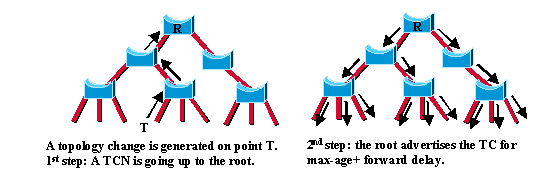
Once the root bridge is aware of a change in the topology of the network, it sets the TC flag on the BPDUs it sends out, which are then relayed to all the bridges in the network. When a bridge receives a BPDU with the TC flag bit set, it reduces its bridging-table aging time to forward delay seconds. This ensures a relatively quick flush of stale information. Refer to Understanding Spanning-Tree Protocol Topology Changes for more information on this process. This topology change mechanism is deeply remodeled in RSTP. Both the detection of a topology change and its propagation through the network evolve.
Topology Change Detection
In RSTP, only non-edge ports that move to the forwarding state cause a topology change. This means that a loss of connectivity is not considered as a topology change any more, contrary to 802.1D (that is, a port that moves to blocking no longer generates a TC). When a RSTP bridge detects a topology change, these occur:
It starts the TC While timer with a value equal to twice the hello-time for all its non-edge designated ports and its root port, if necessary.
It flushes the MAC addresses associated with all these ports.