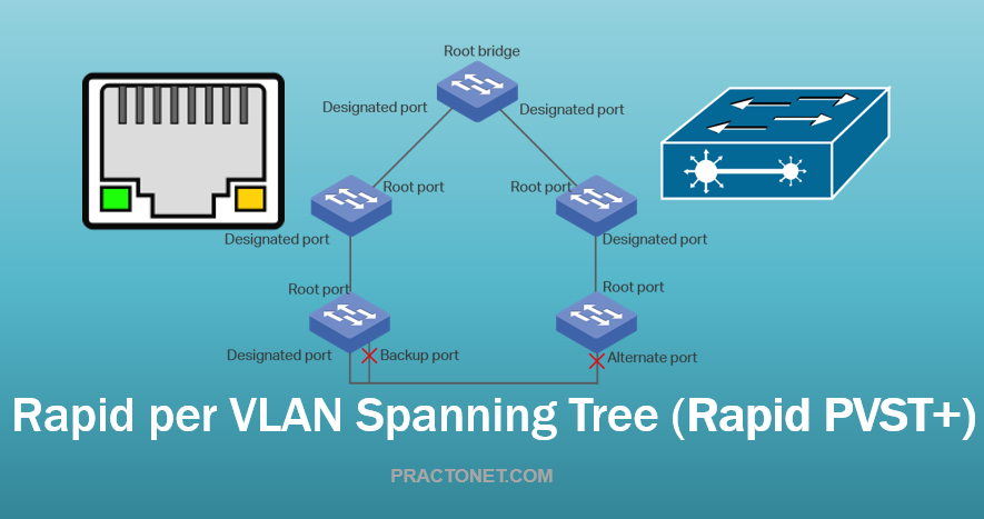
Rapid PVST+ is the IEEE 802.1w (RSTP) standard implemented per VLAN. A single instance of STP runs on each configured VLAN (if you do not manually disable STP). Each Rapid PVST+ instance on a VLAN has a single root switch. You can enable and disable STP on a per-VLAN basis when you are running Rapid PVST+ . Rapid PVST+ uses point-to-point wiring to provide rapid convergence of the spanning tree. The spanning tree reconfiguration can occur in less than 1 second with Rapid PVST+ (in contrast to 50 seconds with the default settings in the 802.1D STP).
Note: Rapid PVST+ is the default STP mode for the switch. Rapid PVST+ supports one STP instance for each VLAN.
Using Rapid PVST+, STP convergence occurs rapidly. Each designated or root port in the STP sends out a BPDU every 2 seconds by default. On a designated or root port in the topology, if hello messages are missed three consecutive times, or if the maximum age expires, the port immediately flushes all protocol information in the table. A port considers that it loses connectivity to its direct neighbor root or designated port if it misses three BPDUs or if the maximum age expires. This rapid aging of the protocol information allows quick failure detection. The switch automatically checks the PVID. Rapid PVST+ provides for rapid recovery of connectivity following the failure of a network device, a switch port, or a LAN. It provides rapid convergence for edge ports, new root ports, and ports connected through point-to-point links as follows:
- Edge ports—When you configure a port as an edge port on an RSTP switch, the edge port immediately transitions to the forwarding state. (This immediate transition was previously a Cisco-proprietary feature named PortFast.) You should only configure on ports that connect to a single end station as edge ports. Edge ports do not generate topology changes when the link changes. Enter the spanning-tree port type interface configuration command to configure a port as an STP edge port.
- Root ports—If Rapid PVST+ selects a new root port, it blocks the old root port and immediately transitions the new root port to the forwarding state.
- Point-to-point links—If you connect a port to another port through a point-to-point link and the local port becomes a designated port, it negotiates a rapid transition with the other port by using the proposal-agreement handshake to ensure a loop-free topology.
Rapid PVST+ achieves rapid transition to the forwarding state only on edge ports and point-to-point links. Although the link type is configurable, the system automatically derives the link type information from the duplex setting of the port. Full-duplex ports are assumed to be point-to-point ports, while half-duplex ports are assumed to be shared ports. Edge ports do not generate topology changes, but all other designated and root ports generate a topology change (TC) BPDU when they either fail to receive three consecutive BPDUs from the directly connected neighbor or the maximum age times out. At this point, the designated or root port sends out a BPDU with the TC flag set. The BPDUs continue to set the TC flag as long as the TC While timer runs on that port. The value of the TC While timer is the value set for the hello time plus 1 second. The initial detector of the topology change immediately floods this information throughout the entire topology.
When Rapid PVST+ detects a topology change, the protocol does the following:
- Starts the TC While timer with a value equal to twice the hello time for all the non-edge root and designated ports, if necessary.
- Flushes the MAC addresses associated with all these ports.
The topology change notification floods quickly across the entire topology. The system flushes dynamic entries immediately on a per-port basis when it receives a topology change.
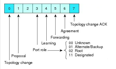
Rapid PVST+ BPDUs
Rapid PVST+ and 802.1w use all six bits of the flag byte to add the role and state of the port that originates the BPDU, and the proposal and agreement handshake. Figure shows the use of the BPDU flags in Rapid PVST+. Another important change is that the Rapid PVST+ BPDU is type 2, version 2, which makes it possible for the switch to detect connected legacy (802.1D) bridges. The BPDU for 802.1D is version 0.
Proposal and Agreement Handshake
As shown, switch A is connected to switch B through a point-to-point link, and all of the ports are in the blocking state. Assume that the priority of switch A is a smaller numerical value than the priority of switch B.
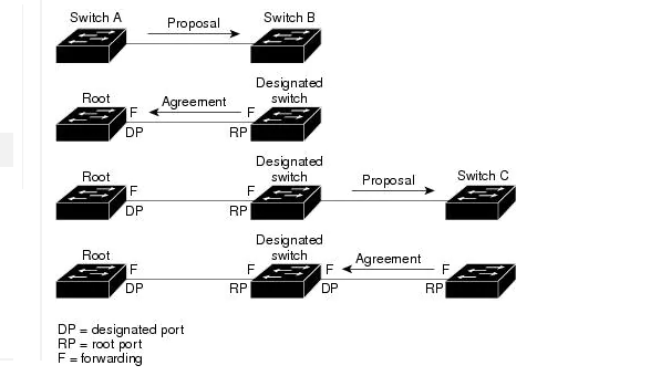
Switch A sends a proposal message (a configuration BPDU with the proposal flag set) to switch B, proposing itself as the designated switch. After receiving the proposal message, switch B selects as its new root port the port from which the proposal message was received, forces all non-edge ports to the blocking state, and sends an agreement message (a BPDU with the agreement flag set) through its new root port. After receiving the agreement message from switch B, switch A also immediately transitions its designated port to the forwarding state. No loops in the network can form because switch B blocked all of its non-edge ports and because there is a point-to-point link between switches A and B.
When switch C connects to switch B, a similar set of handshaking messages are exchanged. Switch C selects the port connected to switch B as its root port, and both ends of the link immediately transition to the forwarding state. With each iteration of this handshaking process, one more network device joins the active topology. As the network converges, this proposal-agreement handshaking progresses from the root toward the leaves of the spanning tree.
The switch learns the link type from the port duplex mode: a full-duplex port is considered to have a point-to-point connection and a half-duplex port is considered to have a shared connection. You can override the default setting that is controlled by the duplex setting by entering the spanning-tree link-type interface configuration command. This proposal/agreement handshake is initiated only when a non-edge port moves from the blocking to the forwarding state. The handshaking process then proliferates step-by-step throughout the topology.
Protocol Timers
Hello timer:
Determines how often each switch broadcasts BPDUs to other switches. The default is 2 seconds, and the range is from 1 to 10.
Forward delay timer:
Determines how long each of the listening and learning states last before the port begins forwarding. This timer is generally not used by the protocol but is used as a backup. The default is 15 seconds, and the range is from 4 to 30 seconds.
Maximum age timer:
Determines the amount of time protocol information received on an port is stored by the switch. This timer is generally not used by the protocol, but it is used when interoperating with 802.1D spanning tree. The default is 20 seconds; the range is from 6 to 40 seconds.
Port Roles
Rapid PVST+ provides rapid convergence of the spanning tree by assigning port roles and learning the active topology. Rapid PVST+ builds upon the 802.1D STP to select the switch with the highest priority (lowest numerical priority value) as the root bridge. Rapid PVST+ then assigns one of these port roles to individual ports:
- Root port—Provides the best path (lowest cost) when the switch forwards packets to the root bridge.
- Designated port—Connects to the designated switch, which incurs the lowest path cost when forwarding packets from that LAN to the root bridge. The port through which the designated switch is attached to the LAN is called the designated port.
- Alternate port—Offers an alternate path toward the root bridge to the path provided by the current root port. An alternate port provides a path to another switch in the topology.
- Backup port—Acts as a backup for the path provided by a designated port toward the leaves of the spanning tree. A backup port can exist only when two ports are connected in a loopback by a point-to-point link or when a switch has two or more connections to a shared LAN segment. A backup port provides another path in the topology to the switch.
- Disabled port—Has no role within the operation of the spanning tree.
In a stable topology with consistent port roles throughout the network, Rapid PVST+ ensures that every root port and designated port immediately transition to the forwarding state while all alternate and backup ports are always in the blocking state. Designated ports start in the blocking state. The port state controls the operation of the forwarding and learning processes.
Rapid PVST+ Port State
Propagation delays can occur when protocol information passes through a switched LAN. As a result, topology changes can take place at different times and at different places in a switched network. When a LAN port transitions directly from nonparticipation in the spanning tree topology to the forwarding state, it can create temporary data loops. Ports must wait for new topology information to propagate through the switched LAN before starting to forward frames.
Each LAN port on a software using Rapid PVST+ or MST exists in one of the following four states:
- Blocking—The LAN port does not participate in frame forwarding.
- Learning—The LAN port prepares to participate in frame forwarding.
- Forwarding—The LAN port forwards frames.
- Disabled—The LAN port does not participate in STP and is not forwarding frames.
When you enable Rapid PVST+, every port in the software, VLAN, and network goes through the blocking state and the transitory states of learning at power up. If properly configured, each LAN port stabilizes to the forwarding or blocking state. When the STP algorithm places a LAN port in the forwarding state, the following process occurs:
- The LAN port is put into the blocking state while it waits for protocol information that suggests it should go to the learning state.
- The LAN port waits for the forward delay timer to expire, moves the LAN port to the learning state, and restarts the forward delay timer.
- In the learning state, the LAN port continues to block frame forwarding as it learns the end station location information for the forwarding database.
- The LAN port waits for the forward delay timer to expire and then moves the LAN port to the forwarding state, where both learning and frame forwarding are enabled.
Blocking State
• Discards frames received from the attached segment.
• Discards frames switched from another port for forwarding.
• Does not incorporate the end station location into its address database. (There is no learning on a blocking LAN port, so there is no address database update.)
• Receives BPDUs and directs them to the system module.
• Receives, processes, and transmits BPDUs received from the system module.
• Receives and responds to network management messages.
Learning State
• Discards frames received from the attached segment.
• Discards frames switched from another port for forwarding.
• Incorporates the end station location into its address database.
• Receives BPDUs and directs them to the system module.
• Receives, processes, and transmits BPDUs received from the system module.
• Receives and responds to network management messages.
Forwarding State
• Forwards frames received from the attached segment.
• Forwards frames switched from another port for forwarding
• Incorporates the end station location information into its address database.
• Receives BPDUs and directs them to the system module.
• Processes BPDUs received from the system module.
• Receives and responds to network management messages
Disabled State
• Discards frames received from the attached segment.
• Discards frames switched from another port for forwarding.
• Does not incorporate the end station location into its address database. (There is no learning, so there is no address database update.)
• Does not receive BPDUs from neighbors.
• Does not receive BPDUs for transmission from the system module.
Synchronization of Port Roles
When the switch receives a proposal message on one of its ports and that port is selected as the new root port, Rapid PVST+ forces all other ports to synchronize with the new root information. The switch is synchronized with superior root information received on the root port if all other ports are synchronized. An individual port on the switch is synchronized if either of the following applies:
- That port is in the blocking state.
- It is an edge port (a port configured to be at the edge of the network).
If a designated port is in the forwarding state and is not configured as an edge port, it transitions to the blocking state when the Rapid PVST+ forces it to synchronize with new root information. In general, when the Rapid PVST+ forces a port to synchronize with root information and the port does not satisfy any of the above conditions, its port state is set to blocking. After ensuring that all of the ports are synchronized, the switch sends an agreement message to the designated switch that corresponds to its root port. When the switches connected by a point-to-point link are in agreement about their port roles, Rapid PVST+ immediately transitions the port states to the forwarding state.

Processing Superior BPDU Information
A superior BPDU is a BPDU with root information (such as a lower switch ID or lower path cost) that is superior to what is currently stored for the port. If a port receives a superior BPDU, Rapid PVST+ triggers a reconfiguration. If the port is proposed and is selected as the new root port, Rapid PVST+ forces all the other ports to synchronize. If the received BPDU is a Rapid PVST+ BPDU with the proposal flag set, the switch sends an agreement message after all of the other ports are synchronized. The new root port transitions to the forwarding state as soon as the previous port reaches the blocking state.
If the superior information received on the port causes the port to become a backup port or an alternate port, Rapid PVST+ sets the port to the blocking state and sends an agreement message. The designated port continues sending BPDUs with the proposal flag set until the forward-delay timer expires. At that time, the port transitions to the forwarding state.
Processing Inferior BPDU Information
An inferior BPDU is a BPDU with root information (such as a higher switch ID or higher path cost) that is inferior to what is currently stored for the port. If a designated port receives an inferior BPDU, it immediately replies with its own information.
Enabling Rapid PVST+
switch# configure terminal
switch(config)# spanning-tree mode rapid-pvst
Enabling Rapid PVST+ per VLAN
switch# configure terminal
switch(config)# spanning-tree vlan 5
To disable,switch(config)# no spanning-tree vlan-range
Configuring the Root Bridge ID
switch# configure terminal
switch(config)# spanning-tree vlan 5 root primary diameter 4
Note: Configures a software switch as the primary root bridge. The vlan-range value can be 2 through 4094 (except reserved VLAN values.) The dia default is 7. The hello-time can be from 1 to 10 seconds, and the default value is 2 seconds.
Configuring a Secondary Root Bridge
switch# configure terminal
switch(config)# spanning-tree vlan 5 root secondary diameter 4
Configuring the Rapid PVST+ Port Priority
You can assign lower priority values to LAN ports that you want Rapid PVST+ to select first and higher priority values to LAN ports that you want Rapid PVST+ to select last. If all LAN ports have the same priority value, Rapid PVST+ puts the LAN port with the lowest LAN port number in the forwarding state and blocks other LAN ports. The software uses the port priority value when the LAN port is configured as an access port and uses VLAN port priority values when the LAN port is configured as a trunk port.switch# configure terminal
switch(config)# interface ethernet 1/4
switch(config-if)# spanning-tree port-priority 160
Configuring the Rapid PVST+ Pathcost Method and Port Cost
On access ports, you assign port cost by the port. On trunk ports, you assign the port cost by VLAN; you can configure the same port cost on all the VLANs on a trunk.switch# configure terminal
switch (config)# spanning-tree pathcost method long
switch (config)# interface ethernet 1/4
switch(config-if)# spanning-tree cost 1000
Configuring the Rapid PVST+ Bridge Priority of a VLAN
switch# configure terminal
switch(config)# spanning-tree vlan 5 priority 8192
Configures the bridge priority of a VLAN. Valid values are 0, 4096, 8192, 12288, 16384, 20480, 24576, 28672, 32768, 36864, 40960, 45056, 49152, 53248, 57344, and 61440. All other values are rejected. The default value is 32768.
Configuring the Rapid PVST+ Hello Time for a VLAN
switch# configure terminal
switch(config)# spanning-tree vlan 5 hello-time 7
Configuring the Rapid PVST+ Forward Delay Time for a VLAN
switch# configure terminal
switch(config)# spanning-tree vlan 5 forward-time 21
Verifying Rapid PVST+ Configurations
switch# show running-config spanning-tree – Displays the current spanning tree configuration.switch# show spanning-tree brief – Displays selected detailed information for the spanning tree configuration.
Switch# Show spanning-tree brief

VLAN001
Spanning tree enabled protocol rstp
Root ID Prioroty 32768
Address 001c.b05a.5447
Cost 2
Port 131 (Ethernet1/3)
Hello Time 2 sec max Age 20 se Forward Delay 15 sc

Bridge Id Priority 32769 (priority 32768 sys-id-ext 1)
Adddress 000d.ec6d.7841
Hell Time 2 sec Max Age 20 sec Forward Delay 15 sec

Interface   Rol     sts  Cost   Prio    .Nbr Type
----------------------------------------------------
Eth1/3      Root    FWD  2      128.131 P2p Peer(STP)
veth1/1     desg    FWD  2      128.129 Edge P2p


