
A Cisco Access Point (AP) is configured to operate in either Lightweight mode or Autonomous mode. A Cisco LAP is part of the Cisco Unified Wireless Network architecture. An LAP is an AP designed to be connected to a wireless LAN controller (WLC). The WLC manages the AP configurations and firmware; therefore, the LAP cannot act independently of a WLC. This mode is sometimes called controller-based. Enterprise Networking and Security content require lightweight mode. On a lightweight AP, the MAC function is divided between the AP hardware and the wireless LAN controller (WLC).
Autonomous AP Architecture
An access point’s primary function is to bridge wireless data from the air to a normal wired network. An AP can accept “connections” from a number of wireless clients so that they become members of the LAN, as if the same clients were using wired connections. APs act as the central point of access (hence the AP name), controlling client access to the wireless LAN. An autonomous AP is self-contained; it is equipped with both wired and wireless hardware so that the wireless client associations can be terminated onto a wired connection locally at the AP. The APs and their data connections must be distributed across the coverage area and across the network.
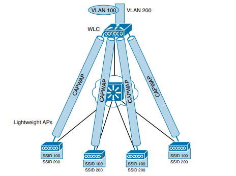
Autonomous APs offer one or more fully functional, standalone basic service sets (BSSs). They are also a natural extension of a switched network, connecting wireless service set identifiers (SSIDs) to wired virtual LANs (VLANs) at the access layer. Below topology shows the basic architecture; even though only four APs are shown across the bottom, a typical enterprise network could consist of hundreds or thousands of APs.
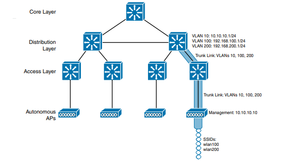
An autonomous AP offers a short and simple path for data to travel between the wireless and wired networks. Data has to travel only through the AP to reach the network on the other side. Two wireless users that are associated to the same autonomous AP can reach each other through the AP without having to pass up into the wired network. As you work through the wireless architectures discussed in the rest of the chapter, notice the data path that is required for each.
What exactly does an autonomous AP need to become a part of the network? The wireless network in above topology consists of two SSIDs: wlan100 and wlan200. These correspond to wired VLANs 100 and 200, respectively. As shown by the shaded links, the VLANs must be trunked from the distribution layer switch (where routing commonly takes place) to the access layer, where they are extended further over a trunk link to the AP.
An autonomous AP must also be configured with a management IP address (10.10.10.10 in above topology) so that you can remotely manage it. After all, you will want to configure SSIDs, VLANs, and many RF parameters like the channel and transmit power to be used. The management address is not normally part of any of the data VLANs, so a dedicated management VLAN (i.e., VLAN 10) must be added to the trunk links to reach the AP. Each AP must be configured and maintained individually unless you leverage a management platform such as Cisco Prime Infrastructure or Cisco DNA Center.
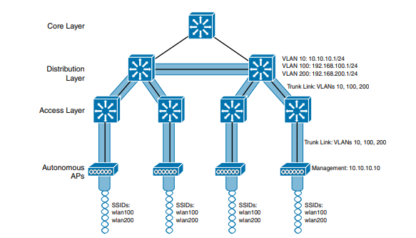
Because the data and management VLANs may need to reach every autonomous AP, the network configuration and efficiency can become cumbersome as the network scales. Because SSIDs and their VLANs must be extended at Layer 2, you should consider how they are extended throughout the switched network. The shaded links in below topology show an example of a single VLAN’s extent in the data plane. Working top to bottom, follow VLAN 100 as it reaches through the network. VLAN 100 is routed within the distribution layer and must be carried over trunk links to the access layer switches and then to each autonomous AP. In effect, VLAN 100 must extend end to end across the whole infrastructure—something that is usually considered to be a bad practice.
Cloud-based AP Architecture
Recall that an autonomous AP needs quite a bit of configuration and management. To help manage more and more autonomous APs as the wireless network grows, you could place an AP management platform such as Cisco Prime Infrastructure in a central location within the enterprise. The management platform would need to be purchased, configured, and maintained too. A simpler approach is a cloud-based AP architecture, where the AP management function is pushed out of the enterprise and into the Internet cloud. Cisco Meraki is cloud-based and offers centralized management of wireless, switched, and security networks built from Meraki products. For example, through the cloud networking service, you can configure and manage APs, monitor wireless performance and activity, generate reports, and so on.
Cisco Meraki APs can be deployed automatically, once you register with the Meraki cloud. Each AP will contact the cloud when it powers up and will self-configure. From that point on, you can manage the AP through the Meraki cloud dashboard. Below image illustrates the basic cloud-based architecture. Notice that the network is arranged identically to that of the autonomous AP network. The reason is that the APs in a cloud-based network are all autonomous, too. The most visible difference is that all of the APs are managed, controlled, and monitored centrally from the cloud.
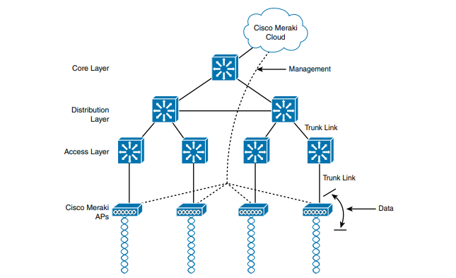
From the cloud, you can push out code upgrades and configuration changes to the APs in the enterprise. The Cisco Meraki cloud also adds the intelligence needed to automatically instruct each AP on which channel and transmit power level to use. It can also collect information from all of the APs about things such as RF interference, rogue or unexpected wireless devices that were overheard, and wireless usage statistics. Finally, there are a couple of things you should observe about the cloud-based architecture. The data path from the wireless network to the wired network is very short; the autonomous AP links the two networks. Data to and from wireless clients does not have to travel up into the cloud and back; the cloud is used to bring management functions into the data plane.
Also, notice that the network in above topology consists of two distinct paths—one for data traffic and another for management traffic, corresponding to the following two functions:
- A control plane: Traffic used to control, configure, manage, and monitor the AP itself
- A data plane: End-user traffic passing through the AP
Split-MAC Architectures
Managing wireless network security can also be difficult. Each autonomous AP handles its own security policies, with no central point of entry between the wireless and wired networks. That means there is no convenient place to monitor traffic for things such as intrusion detection and prevention, quality of service, bandwidth policing, and so on. To overcome the limitations of distributed autonomous APs, many of the functions found within autonomous APs have to be shifted toward some central location.
In below Figure, most of the activities performed by an autonomous AP on the left are broken up into two groups—management functions on the top and real-time processes on the bottom.
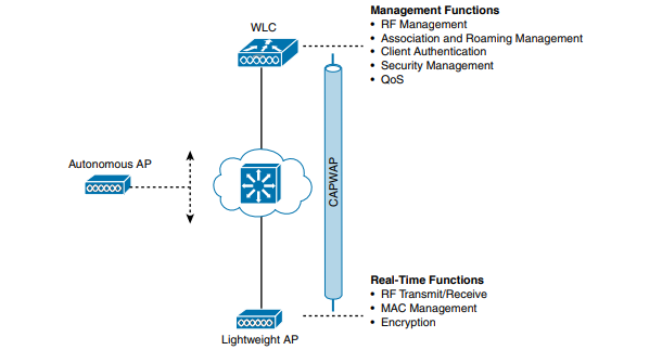
The real-time processes involve sending and receiving 802.11 frames, beacons, and probe messages. 802.11 data encryption is also handled in real time, on a per-packet basis. The AP must interact with wireless clients on some low level, known as the Media Access Control (MAC) layer. These functions must stay with the AP hardware, closest to the clients. The management functions are not integral to handling frames over the RF channels, but are things that should be centrally administered. Therefore, those functions can be moved to a centrally located platform away from the AP.
When the functions of an autonomous AP are divided, the AP hardware is known as a lightweight access point, and performs only the real-time 802.11 operation. The lightweight AP gets its name because the code image and the local intelligence are stripped down, or lightweight, compared to the traditional autonomous AP. The management functions are usually performed on a wireless LAN controller (WLC), which controls many lightweight APs. This is shown in the bottom right portion of Figure above. Notice that the AP is left with duties in Layers 1 and 2, where frames are moved into and out of the RF domain. The AP becomes totally dependent on the WLC for every other WLAN function, such as authenticating users, managing security policies, and even selecting RF channels and output power.
The lightweight AP-WLC division of labor is known as a split-MAC architecture, where the normal MAC operations are pulled apart into two distinct locations. This occurs for every AP in the network; each one must boot and bind itself to a WLC to support wireless clients. The WLC becomes the central hub that supports a number of APs scattered about in the network. How does a lightweight AP bind with a WLC to form a complete working access point? The two devices must use a tunneling protocol between them, to carry 802.11-related messages and also client data. Remember that the AP and WLC can be located on the same VLAN or IP subnet, but they do not have to be. Instead, they can be located on two entirely different IP subnets in two entirely different locations.
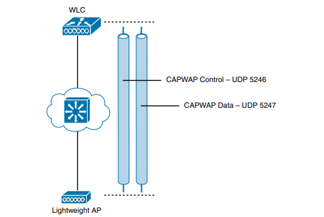
The Control and Provisioning of Wireless Access Points (CAPWAP) tunneling protocol makes this all possible by encapsulating the data between the LAP and WLC within new IP packets. The tunneled data can then be switched or routed across the campus network. As Figure below shows, the CAPWAP relationship actually consists of two separate tunnels, as follows:
- CAPWAP control messages: Carries exchanges that are used to configure the AP and manage its operation. The control messages are authenticated and encrypted, so the AP is securely controlled by only the appropriate WLC, then transported over the control tunnel.
- CAPWAP data: Used for packets traveling to and from wireless clients that are associated with the AP. Data packets are transported over the data tunnel but are not encrypted by default. When data encryption is enabled for an AP, packets are protected with Datagram Transport Layer Security (DTLS).
The CAPWAP tunneling allows the AP and WLC to be separated geographically and logically. It also breaks the dependence on Layer 2 connectivity between them. Also, notice how the AP is known by only a single IP address: 10.10.10.10. Because the AP sits on the access layer where its CAPWAP tunnels terminate, it can use one IP address for both management and tunneling. No trunk link is needed because all of the VLANs it supports are encapsulated and tunneled as Layer 3 IP packets, rather than individual Layer 2 VLANs. As the wireless network grows, the WLC simply builds more CAPWAP tunnels to reach more APs.
Once CAPWAP tunnels are built from a WLC to one or more lightweight APs, the WLC can begin offering a variety of additional functions. Think of all the puzzles and shortcomings that were discussed for the traditional autonomous WLAN architecture as you read over the following list of WLC activities:
- Dynamic channel assignment: The WLC can automatically choose and configure the RF channel used by each AP, based on other active access points in the area.
- Transmit power optimization: The WLC can automatically set the transmit power of each AP based on the coverage area needed.
- Self-healing wireless coverage: If an AP radio dies, the coverage hole can be “healed” by turning up the transmit power of surrounding APs automatically.
- Flexible client roaming: Clients can roam between APs with very fast roaming times.
- Dynamic client load balancing: If two or more APs are positioned to cover the same geographic area, the WLC can associate clients with the least used AP. This distributes the client load across the APs.
- RF monitoring: The WLC manages each AP so that it scans channels to monitor the RF usage. By listening to a channel, the WLC can remotely gather information about RF interference, noise, signals from neighboring APs, and signals from rogue APs or ad hoc clients.
- Security management: The WLC can authenticate clients from a central service and can require wireless clients to obtain an IP address from a trusted DHCP server before allowing them to associate and access the WLAN.
- Wireless intrusion protection system: Leveraging its central location, the WLC can monitor client data to detect and prevent malicious activity.
Cisco AP Modes
Many Cisco APs can operate in either autonomous or lightweight mode, depending on which code image is loaded and run. From the WLC, you can also configure a lightweight AP to operate in one of the following special-purpose modes:
- Local: The default lightweight mode that offers one or more functioning BSSs on a specific channel. During times that it is not transmitting, the AP will scan the other channels to measure the level of noise, measure interference, discover rogue devices, and match against intrusion detection system (IDS) events. <
- Monitor: The AP does not transmit at all, but its receiver is enabled to act as a dedicated sensor. The AP checks for IDS events, detects rogue access points, and determines the position of stations through location-based services.
- FlexConnect: An AP at a remote site can locally switch traffic between an SSID and a VLAN if its CAPWAP tunnel to the WLC is down and if it is configured to do so.
- Sniffer: An AP dedicates its radios to receiving 802.11 traffic from other sources, much like a sniffer or packet capture device. The captured traffic is then forwarded to a PC running network analyzer software such as Wildpackets OmniPeek or WireShark, where it can be analyzed further.
- Rogue detector: An AP dedicates itself to detecting rogue devices by correlating MAC addresses heard on the wired network with those heard over the air. Rogue devices are those that appear on both networks.
- Bridge: An AP becomes a dedicated bridge (point-to-point or point-to-multipoint) between two networks. Two APs in bridge mode can be used to link two locations separated by a distance. Multiple APs in bridge mode can form an indoor or outdoor mesh network.
- Flex+Bridge: FlexConnect operation is enabled on a mesh AP.
- SE-Connect: The AP dedicates its radios to spectrum analysis on all wireless channels. You can remotely connect a PC running software such as MetaGeek Chanalyzer or Cisco Spectrum Expert to the AP to collect and analyze the spectrum analysis data to discover sources of interference.


