
In Cisco, there are two types of Wireless Solutions. One of them is using only Autonomous Access Points and the other is using Light Weight Access Points (LWAP) with Wireless LAN Controllers. So, What are Access Points? What is a WLC? Let’s learn each of these devices in Wireless Networks.
Connecting a Cisco AP
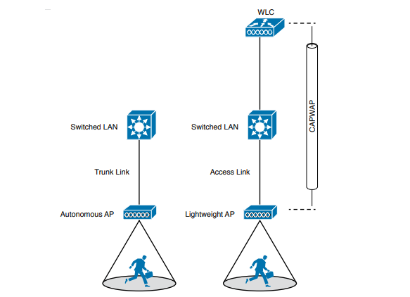
A Cisco wireless network can consist of autonomous APs or lightweight APs that are coupled with one or more wireless LAN controllers. Recall that an autonomous AP is a standalone device; nothing else is needed to forward Ethernet frames from a wired VLAN to a wireless LAN, and vice versa. In effect, the AP maps each VLAN to a WLAN and BSS. The autonomous AP has a single wired Ethernet interface, which means that multiple VLANs must be brought to it over a trunk link.
A lightweight AP also has a single wired Ethernet interface; however, it must be paired with a WLC to be fully functional. Wired VLANs that terminate at the WLC can be mapped to WLANs that emerge at the AP. Even though multiple VLANs are being extended from the WLC to the AP, they are all carried over the CAPWAP tunnel between the two. That means the AP needs only an access link to connect to the network infrastructure and terminate its end of the tunnel.
Note: A switch port providing a wired connection to an AP must be configured to support either access or trunk mode. In trunk mode, 802.1Q encapsulation tags each frame according to the VLAN number it came from. The wireless side of an AP inherently trunks 802.11 frames by marking them with the BSSID of the WLAN where they belong.
To configure and manage Cisco APs, you can connect a serial console cable from your PC to the console port on the AP. Once the AP is operational and has an IP address, you can also use Telnet or SSH to connect to its CLI over the wired network. Autonomous APs support browser-based management sessions via HTTP and HTTPS. You can manage lightweight APs from a browser session to the WLC.
Accessing a Cisco WLC
To connect and configure a WLC, you will need to open a web browser to the WLC’s management address with either HTTP or HTTPS. This can be done only after the WLC has an initial configuration and a management IP address assigned to its management interface. The web-based GUI provides an effective way to monitor, configure, and troubleshoot a wireless network. You can also connect to a WLC with an SSH session, where you can use its CLI to monitor, configure, and debug activity.
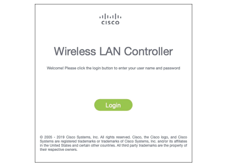
Both the web-based GUI and the CLI require management users to log in. Users can be authenticated against an internal list of local usernames or against an authentication, authorization, and accounting (AAA) server, such as TACACS+ or RADIUS. When you first open a web browser to the management address, you will see the initial login screen. Click on the Login button, then enter your user credentials as you are prompted for them.
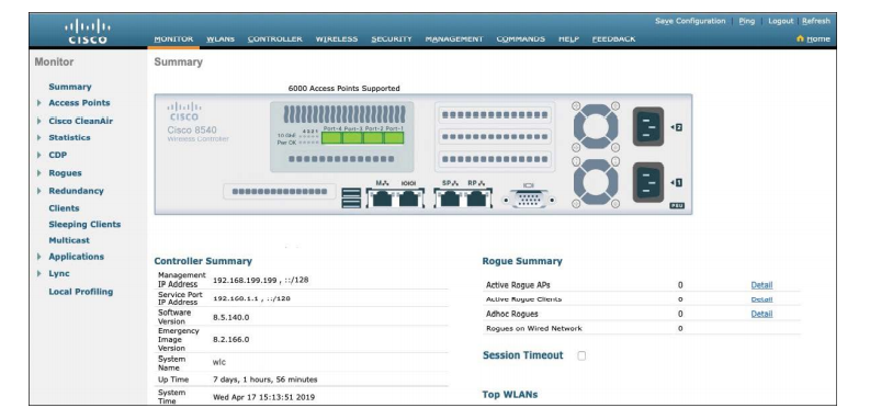
When you are successfully logged in, the WLC will display a monitoring dashboard. You will not be able to make any configuration changes there, so you must click on the Advanced link in the upper-right corner. This will bring up the full WLC GUI. Notice the tabs across the top of the screen in second picture. You can select categories of functions from among Monitor, WLANs, Controller, Wireless, Security, and so on. As you select one of these categories, the vertical list of functions at the left side of the screen will change accordingly. You can expand the list entries if needed and select one to work on. The main screen area will display all of the relevant fields and options you can edit as you make configuration changes.

Connecting a Cisco WLC
Connecting a Cisco wireless LAN controller to the network is not quite as straightforward because it has several different types of connections. From your work with Cisco routers and switches, you probably know that the terms interface and port are usually interchangeable. For example, switches can come in 48-port models, and you apply configuration changes to the corresponding interfaces. Cisco wireless controllers differ a bit; ports and interfaces refer to different concepts.
Controller ports are physical connections made to an external wired or switched network, whereas interfaces are logical connections made internally within the controller.
Using WLC Ports
You can connect several different types of controller ports to your network, as discussed in the following list:
- Service port: Used for out-of-band management, system recovery, and initial boot functions; always connects to a switch port in access mode
- Distribution system port: Used for all normal AP and management traffic; usually connects to a switch port in 802.1Q trunk mode
- Console port: Used for out-of-band management, system recovery, and initial boot functions; asynchronous connection to a terminal emulator (9600 baud, 8 data bits, 1 stop bit, by default)
- Redundancy port: Used to connect to a peer controller for high availability (HA) operation
Controllers can have a single service port that must be connected to a switched network. Usually, the service port is assigned to a management VLAN so that you can access the controller with SSH or a web browser to perform initial configuration or for maintenance. Notice that the service port supports only a single VLAN, so the corresponding switch port must be configured for access mode only.
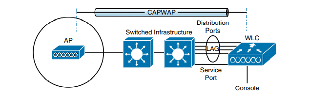
Controllers also have multiple distribution system ports that you must connect to the network. These ports carry most of the data coming to and going from the controller. For example, the CAPWAP tunnels (control and data) that extend to each of a controller’s APs pass across the distribution system ports. Client data also passes from wireless LANs to wired VLANs over the ports. In addition, any management traffic using a web browser, SSH, Simple Network Management Protocol (SNMP), Trivial File Transfer Protocol (TFTP), and so on, normally reaches the controller in-band through the ports.
Because the distribution system ports must carry data that is associated with many different VLANs, VLAN tags and numbers become very important. For that reason, the distribution system ports always operate in 802.1Q trunking mode. When you connect the ports to a switch, you should also configure the switch ports for unconditional 802.1Q trunk mode. The distribution system ports can operate independently, each one transporting multiple VLANs to a unique group of internal controller interfaces. For resiliency, you can configure distribution system ports in redundant pairs. One port is primarily used; if it fails, a backup port is used instead.
To get the most use out of each distribution system port, you can configure all of them to operate as a single logical group, much like an EtherChannel or port-channel on a switch. Controller distribution system ports can be configured as a link aggregation group (LAG) such that they are bundled together to act as one larger link. In above figure the four distribution system ports are configured as a LAG. With a LAG configuration, traffic can be load-balanced across the individual ports that make up the LAG. In addition, LAG offers resiliency; if one individual port fails, traffic will be redirected to the remaining working ports instead.
Using WLC Interfaces
Through its distribution system ports, a controller can connect to multiple VLANs on the switched network. Internally, the controller must somehow map those wired VLANs to equivalent logical wireless networks. For example, suppose that VLAN 10 is set aside for wireless users in the Engineering division of a company. That VLAN must be connected to a unique wireless LAN that exists on a controller and its associated APs. The wireless LAN must then be extended to every client that associates with the Service Set Identifier (SSID) “Practonet”.
Cisco wireless controllers provide the necessary connectivity through internal logical interfaces, which must be configured with an IP address, subnet mask, default gateway, and a Dynamic Host Configuration Protocol (DHCP) server. Each interface is then assigned to a physical port and a VLAN ID. You can think of an interface as a Layer 3 termination on a VLAN.
Cisco controllers support the following interface type:
- Management interface: Used for normal management traffic, such as RADIUS user authentication, WLC-to-WLC communication, web-based and SSH sessions, SNMP, Network Time Protocol (NTP), syslog, and so on. The management interface is also used to terminate CAPWAP tunnels between the controller and its APs.
- Redundancy management: The management IP address of a redundant WLC that is part of a high availability pair of controllers. The active WLC uses the management interface address, while the standby WLC uses the redundancy management address.
- Virtual interface: IP address facing wireless clients when the controller is relaying client DHCP requests, performing client web authentication, and supporting client mobility.
- Service port interface: Bound to the service port and used for out-of-band management.
- Dynamic interface: Used to connect a VLAN to a WLAN
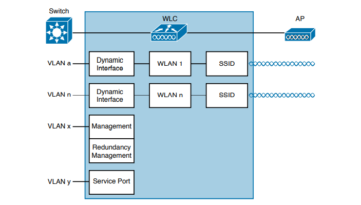
The management interface faces the switched network, where management users and APs are located. Management traffic will usually consist of protocols like HTTPS, SSH, SNMP, NTP, TFTP, and so on. In addition, management interface traffic consists of CAPWAP packets that carry control and data tunnels to and from the APs. The virtual interface is used only for certain client-facing operations. For example, when a wireless client issues a request to obtain an IP address, the controller can relay the request on to an actual DHCP server that can provide the appropriate IP address. From the client’s perspective, the DHCP server appears to be the controller’s virtual interface address. Clients may see the virtual interface’s address, but that address is never used when the controller communicates with other devices on the switched network.


