SSH (Secure Shell) is a protocol which define how to connect securely over a network. SSH (Secure Shell) protocol provides the three main ideas of security authentication, confidentiality (via encryption) and integrity of data transfer over a network. SSH supports Authentication to reliably determine the identity of the connecting computer, encryption to scramble data so that only the intended recipient only can read it and Integrity to guarantees the data sent over the network is not changed by a third party.
SSH has two main versions, SSH1 and SSH2. Both SSH1 and SSH2 supports secure connection over network, but SSH2 supports for public key certificates and Diffie-Hellman key exchange. SSH uses TCP as its transport layer protocol and uses well-known port number 22.
Enabling IPv4 for Remote Access
To allow Telnet or SSH access to the switch, and to allow other IP-based management protocols (for example, Simple Network Management Protocol, or SNMP) to function as intended, the switch needs an IP address, as well as a few other related settings. The IP address has nothing to do with how switches forward Ethernet frames; it simply exists to support overhead management traffic.
Host and Switch IP Settings
A switch needs the same kind of IP settings as a PC with a single Ethernet interface. For perspective, a PC has a CPU, with the operating system running on the CPU. It has an Ethernet network interface card (NIC). The OS configuration includes an IP address associated with the NIC, either configured or learned dynamically with DHCP.
A switch uses the same ideas, except that the switch needs to use a virtual NIC inside the switch. Like a PC, a switch has a real CPU, running an OS (called IOS). The switch obviously has lots of Ethernet ports, but instead of assigning its management IP address to any of those ports, the switch then uses a NIC-like concept called a switched virtual interface (SVI), or more commonly, a VLAN interface, that acts like the switch’s own NIC. Then the settings on the switch look something like a host, with the switch configuration assigning IP settings, like an IP address, to this VLAN interface.
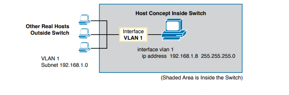
By using interface VLAN 1 for the IP configuration, the switch can then send and receive frames on any of the ports in VLAN 1. In a Cisco switch, by default, all ports are assigned to VLAN 1. In most networks, switches configure many VLANs, so the network engineer has a choice of where to configure the IP address. That is, the management IP address does not have to be configured on the VLAN 1 interface (as configured with the interface vlan 1 command).
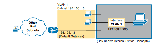
A Layer 2 Cisco LAN switch needs only one IP address for management purposes. However, you can choose to use any VLAN to which the switch connects. The configuration then includes a VLAN interface for that VLAN number, with an appropriate IP address. Configuring the IP address (and mask) on one VLAN interface allows the switch to send and receive IP packets with other hosts in a subnet that exists on that VLAN; however, the switch cannot communicate outside the local subnet without another configuration setting called the default gateway. The reason a switch needs a default gateway setting is the same reason that hosts need the same setting—because of how hosts think when sending IP packets.
Specifically:
- To send IP packets to hosts in the same subnet, send them directly
- To send IP packets to hosts in a different subnet, send them to the local router; that is, the default gateway
In this case, the switch (on the right) will use IP address 192.168.1.200 as configured on interface VLAN 1. However, to communicate with host A, on the far left of the figure, the switch must use Router R1 (the default gateway) to forward IP packets to host A. To make that work, the switch needs to configure a default gateway setting, pointing to Router R1’s IP address (192.168.1.1 in this case). Note that the switch and router both use the same mask, 255.255.255.0, which puts the addresses in the same subnet.
Configuring IPv4 on a Switch
A switch configures its IPv4 address and mask on this special NIC-like VLAN interface. The following steps list the commands used to configure IPv4 on a switch, assuming that the IP address is configured to be in VLAN 1.
Step 1. Use the interface vlan 1 command in global configuration mode to enter interface VLAN 1 configuration mode.
Step 2. Use the ip address ip-address mask command in interface configuration mode to assign an IP address and mask.
Step 3. Use the no shutdown command in interface configuration mode to enable the VLAN 1 interface if it is not already enabled.
Step 4. Add the ip default-gateway ip-address command in global configuration mode to configure the default gateway.
Step 5. (Optional) Add the ip name-server ip-address1 ip-address2 … command in global configuration mode to configure the switch to use Domain Name System (DNS) to resolve names into their matching IP address
practonet# configure terminal
practonet(config)# interface vlan 1
practonet(config-if)# ip address 192.168.1.200 255.255.255.0
practonet(config-if)# no shutdown
00:25:07: %LINK-3-UPDOWN: Interface Vlan1, changed state to up 00:25:08: %LINEPROTO-5-UPDOWN: Line protocol on Interface Vlan1, changed state to up
practonet(config-if)# exit
practonet(config)# ip default-gateway 192.168.1.1
Configuring a Switch to Learn Its IP Address with DHCP
The switch can also use Dynamic Host Configuration Protocol (DHCP) to dynamically learn its IPv4 settings. Basically, all you have to do is tell the switch to use DHCP on the interface and enable the interface. Assuming that DHCP works in this network, the switch will learn all its settings.
Step 1. Enter VLAN 1 configuration mode using the interface vlan 1 global configuration command, and enable the interface using the no shutdown command as necessary.
Step 2. Assign an IP address and mask using the ip address dhcp interface subcommand.
practonet# configure terminal
Enter configuration commands, one per line. End with CNTL/Z.
practonet(config)# interface vlan 1
practonet(config-if)# ip address dhcp
practonet(config-if)# no shutdown
practonet(config-if)# ^Z
00:38:20: %LINK-3-UPDOWN: Interface Vlan1, changed state to up 00:38:21: %LINEPROTO-5-UPDOWN: Line protocol on Interface Vlan1, changed state to up
[ configure the no ip domain-lookup global configuration command, which disables IOS’s attempt to resolve the hostname into an IP address.]
Configure SSH (Secure Shell) in Cisco Router or Switch for secure remote access
Step 1: First step in configuring SSH to securely access the CLI interface of a Cisco Router or Switch remotely is to create a local user database for user authentication. Follow these steps to create a local user with username “practonet” and password as “practonetpass” and with a privilege level 15.
R1# configure terminal
R1(config)# username practonet privilege 15 secret practonetpass
R1(config)# exit
Step 2: Cisco devices use RSA public key encryption algorithm for SSH connectivity. Before generating RSA encryption keys, you must change the default hostname of a Cisco Router or Switch. The default device name of a Cisco Router is “Router” and default device name of a Cisco Switch is “Switch”. You must configure a domain name also before generating RSA keys.
Follow these Cisco IOS CLI commands to configure a hostname, a domain name and to generate RSA keys of 1024 bit length. After generating the RSA keys, Cisco Router/Switch will automatically enable SSH 1.99. SSH 1.99 shows that Cisco device supports both SSH 2 and SSH 1. SSH 1.99 is not a version, but an indication of backward compatibility.
Router#
Router# configure terminal
Router(config)# hostname R1
R1(config)# ip domain-name practonet.com
R1(config)# crypto key generate rsa general-keys
The name for the keys will be: R1.practonet.com
Choose the size of the key modulus in the range of 360 to 2048 for your General Purpose Keys. Choosing a key modulus greater than 512 may take a few minutes.
How many bits in the modulus [512]: 1024
% Generating 1024 bit RSA keys, keys will be non-exportable...[OK]
*Nov 15 16:54:20.595: %SSH-5-ENABLED: SSH 1.99 has been enabled
R1(config)#exit
R1#
Step 3: Next important step you have to do is to configure router/switch to use local user database for authentication and to disable telnet. Disabling telnet will prevent someone to connect to a Cisco Router or Switch accidentally using telnet and cause a security issue. Follow these steps to instruct the Cisco Router or Switch to use local user database for SSH authentication and to disable telnet access to Cisco Router or Switch.
R1# configure terminal
R1(config)# line vty 0 1869
R1(config-line)# login local
R1(config-line)# transport input ssh
R1(config-line)# exit
R1(config)#
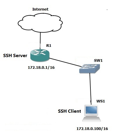
Step 4: To connect to Cisco Router or Cisco Switch using SSH from a Windows workstation, you must use a SSH client tool (SSH client utility is not packed with Windows Operating Systems up to Windows 7). Follow the link to download PuTTY, one of the best terminal emulator software availabe for free.
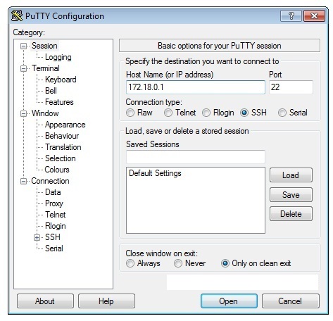
Open PuTTY and enter the IP address of the Cisco Router or Cisco Switch which you want to connect to. Select SSH as the desired protocol as shown below.
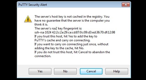
Step 5: If this is the first time you are connecting to the Cisco Router or Cisco Switch, you will get a warning message as shown below stating that the Router’s/Switch’s host key is not cached locally. Accept the warning message and click “Yes” to connect to Cisco Router or Switch.
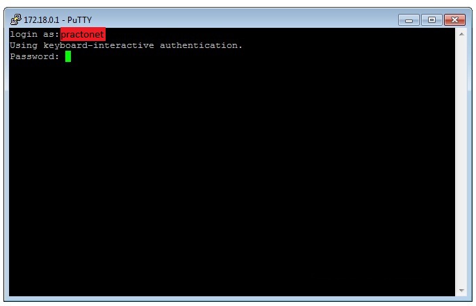
Step 6: Enter the userid (practonet) and corresponding password which we have configured in Cisco Router/Switch before and hit “Enter”
Step 7: Now you are connected to Cisco Router or Switch using SSH protocol. You can now start configuring the Cisco Router/Switch securely from a remote location.