Spanning Tree Protocol (STP) allows Ethernet LANs to have the added benefits of installing redundant links in a LAN, while overcoming the known problems that occur when adding those extra links. Using redundant links in a LAN design allows the LAN to keep working even when some links fail or even when some entire switches fail. Proper LAN design should add enough redundancy so that no single point of failure crashes the LAN; STP allows the design to use redundancy without causing some other problems.
Without some mechanism like Spanning Tree Protocol (STP) or Rapid STP (RSTP), a LAN with redundant links would cause Ethernet frames to loop for an indefinite period of time. With STP or RSTP enabled, some switches block ports so that these ports do not forward frames. STP and RSTP intelligently choose which ports block, with two goals in mind:
- All devices in a VLAN can send frames to all other devices. In other words, STP or RSTP does not block too many ports, cutting off some parts of the LAN from other parts.
- Frames have a short life and do not loop around the network indefinitely.
STP and RSTP strike a balance, allowing frames to be delivered to each device, without causing the problems that occur when frames loop through the network over and over again. STP/RSTP prevents looping frames by adding an additional check on each interface before a switch uses it to send or receive user traffic. That check: If the port is in STP/RSTP forwarding state in that VLAN, use it as normal; if it is in STP/RSTP blocking state, however, block all user traffic and do not send or receive user traffic on that interface in that VLAN. Note that these STP/RSTP states do not change the other information you already know about switch interfaces. The interface’s state of connected/notconnect does not change. The interface’s operational state as either an access or trunk port does not change. STP/RSTP adds this additional state, with the blocking state basically disabling the interface.
In many ways, those last two paragraphs sum up what STP/RSTP does. However, the details of how STP/RSTP does its work can take a fair amount of study and practice. This first major section of the chapter begins by explaining the need for STP/RSTP and the basic ideas of what STP/RSTP does to solve the problem of looping frames. The majority of this section then looks at how STP/RSTP goes about choosing which switch ports to block to accomplish its goals.
The Need for Spanning Tree
STP/RSTP prevents three common problems in Ethernet LANs. All three problems occur as a side effect of one fact: without STP/RSTP, some Ethernet frames would loop around the network for a long time (hours, days, literally forever if the LAN devices and links never failed). Just one looping frame causes what is called a broadcast storm. Broadcast storms happen when any kind of Ethernet frames—broadcast frames, multicast frames, or unknown-destination unicast frames—loop around a LAN indefinitely. Broadcast storms can saturate all the links with copies of that one single frame, crowding out good frames, as well as significantly impacting end-user device performance by making the PCs process too many broadcast frames.
Below shows a sample network in which Bob sends a broadcast frame. The dashed lines show how the switches forward the frame when STP/RSTP does not exist.
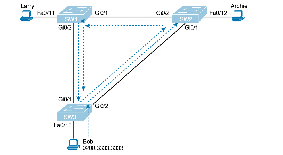
That logic tells switches to flood broadcasts out all interfaces in the same VLAN except the interface in which the frame arrived. That means SW3 forwards Bob’s frame to SW2, SW2 forwards the frame to SW1, SW1 forwards the frame back to SW3, and SW3 forwards it back to SW2 again. When broadcast storms happen, frames like the one keep looping until something changes—someone shuts down an interface, reloads a switch, or does something else to break the loop. Also note that the same event happens in the opposite direction. When Bob sends the original frame, SW3 also forwards a copy to SW1, SW1 forwards it to SW2, and so on. The storm also causes a much more subtle problem called MAC table instability. MAC table instability means that the switches’ MAC address tables keep changing because frames with the same source MAC arrive on different ports. To see why, follow this example, in which SW3 begins Figure with a MAC table entry for Bob, at the bottom of the figure, associated with port Fa0/13:
0200.3333.3333 Fa0/13 VLAN 1
However, now think about the switch-learning process that occurs when the looping frame goes to SW2, then SW1, and then back into SW3’s Gi0/1 interface. SW3 thinks, “Hmm…the source MAC address is 0200.3333.3333, and it came in my Gi0/1 interface. Update my MAC table!” This results in the following entry on SW3, with interface Gi0/1 instead of Fa0/13:
0200.3333.3333 Gi0/1
VLAN 1 At this point, SW3 itself cannot correctly deliver frames to Bob’s MAC address. At that instant, if a frame arrives at SW3 destined for Bob—a different frame than the looping frame that causes the problems—SW3 incorrectly forwards the frame out Gi0/1 to SW1, creating even more congestion.
The looping frames in a broadcast storm also cause a third problem: multiple copies of the frame arrive at the destination. Consider a case in which Bob sends a frame to Larry but none of the switches know Larry’s MAC address. Switches flood frames sent to unknown destination unicast MAC addresses. When Bob sends the frame destined for Larry’s MAC address, SW3 sends a copy to both SW1 and SW2. SW1 and SW2 also flood the frame, causing copies of the frame to loop. SW1 also sends a copy of each frame out Fa0/11 to Larry. As a result, Larry gets multiple copies of the frame, which may result in an application failure, if not more pervasive networking problems.
What Spanning Tree Does
STP/RSTP prevents loops by placing each switch port in either a forwarding state or a blocking state. Interfaces in the forwarding state act as normal, forwarding and receiving frames. However, interfaces in a blocking state do not process any frames except STP/RSTP messages (and some other overhead messages). Interfaces that block do not forward user frames, do not learn MAC addresses of received frames, and do not process received user frames.
Below shows a simple STP/RSTP tree that solves the problem shown in Figure 9-1 by placing one port on SW3 in the blocking state.
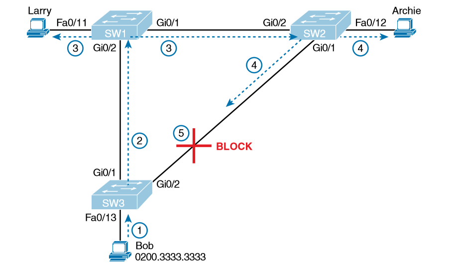
Now when Bob sends a broadcast frame, the frame does not loop. As shown in the steps in the figure:
- Step 1. Bob sends the frame to SW3.
- Step 2. SW3 forwards the frame only to SW1, but not out Gi0/2 to SW2, because SW3’s Gi0/2 interface is in a blocking state.
- Step 3. SW1 floods the frame out both Fa0/11 and Gi0/1.
- Step 4. SW2 floods the frame out Fa0/12 and Gi0/1.
- Step 5. SW3 physically receives the frame, but it ignores the frame received from SW2 because SW3’s Gi0/2 interface is in a blocking state.
Spanning-tree Terms
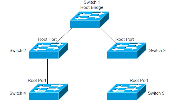
1. Root bridge & Election : The root bridge is the bridge with the lowest and, therefore, the best bridge ID. The switches within the STP network elect a root bridge, which becomes the focal point in the network. All other decisions in the network, like which ports on the non root bridges should be blocked or put in forwarding mode, are made from the perspective of the root bridge, and once it has been elected, all other bridges must create a single path to it. The port with the best path to the root bridge is called the root port.
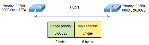
Election is perform on the basis of Bridge ID which is of 8 bytes. In which 2 bytes is of priority and 6 byte is od MAC address. By default priority is 32768. The lower bridge id is preferred for RB. First priority is taken and is it is tie then mac address is seen. In below topology both using the default priority of 32,768, the MAC address will be the determining factor instead. And because Switch A’s MAC address is 0000.0cab.3274 and Switch B’s MAC address is 0000.0cf6.9370, Switch A becomes the root bridge.
2. Non-root bridge : These are all bridges that aren’t the root bridge. Non-root bridges exchange BPDUs with all the other bridges and update the STP topology database on all switches. This prevents loops and helps defend against link failures.
3. BPDU : All switches exchange information to use for the subsequent configuration of the network. Each switch compares the parameters in the Bridge Protocol Data Unit (BPDU) that it sends to a neighbor with the parameters in the BPDU that it receives from other neighbors. Inside the BPDU is the bridge ID.
4. Bridge ID : The bridge ID is how STP keeps track of all the switches in the network. It’s determined by a combination of the bridge priority, which is 32,768 by default on all Cisco switches, and the base MAC address. The bridge with the lowest bridge ID becomes the root bridge in the network. Once the root bridge is established, every other switch must make a single path to it.
5. Path cost : A switch may encounter one or more switches on its path to the Root Bridge, and there may be more than one possible path. All unique paths are analyzed individually, and a path cost is calculated for each unique path by adding the individual port costs encountered on the way to the Root Bridge.
Bridge Port Roles
1. Root port (RP) : The root port is the link with the lowest path cost to the root bridge. If more than one link connects to the root bridge, then a port cost is found by checking the bandwidth of each link. The lowest-cost port becomes the root port. When multiple links connect to the same device, the port connected to the lowest port number on the upstream switch will be the one that’s used. The root bridge can never have a root port designation, while every other switch in a network must have one and only one root port.
2. Designated port (DP) : A designated port is one that’s been determined to have the best i.e lowest cost to get to on a given network segment, compared to other ports on that segment. A designated port will be marked as a forwarding port, and you can have only one forwarding port per network segment.
3. Blocked port : A blocked port won’t forward frames in order to prevent loops. A blocked port will still always listen to BPDU frames from neighbor switches, but it will drop any and all other frames received and will never transmit a frame.
Spanning-Tree Port States
The ports on a bridge or switch can transition data through five different states:
1. Disable : A port in the administratively disabled state doesn’t participate in frame forwarding or STP.
2. Blocked : A blocked port won’t forward frames; it just listens to BPDUs. The purpose of the blocking state is to prevent the use of looped paths. All ports are in blocking state by default when the switch is powered up.
3. Listening : This port listens to BPDUs to make sure no loops occur on the network before passing data frames. A port in listening state prepares to forward data frames without populating the MAC address table. Time taken by this state is 15 Sec to enter learning state.
4. Learning : The switch port listens to BPDUs and learns all the paths in the switched network. A port in learning state populates the MAC address table but still doesn’t forward data frames. Time taken by this state is 15 Sec.
5. Forwarding : This port sends and receives all data frames on the bridged port. If the port is still a designated or root port at the end of the learning state, it will enter the forwarding state. Time taken by this state is 2 Sec.
STP Timers
STP utilizes three timers to ensure all switches remain synchronized, and to allow enough time for the Spanning Tree process to ensure a loop-free environment.
• Hello Timer – Default is 2 seconds. Indicates how often BPDU’s are sent by switches.
• Forward Delay – Default is 15 seconds. Indicates a delay period in both the listening and learning states of a port, for a total of 30 seconds. This delay ensures STP has ample time to detect and eliminate loops.
• Max Age – Default is 20 seconds. Indicates how long a switch will keep BPDU information from a neighboring switch before discarding it. In other words, if a switch fails to receive BPDU’s from a neighboring switch for the Max Age period, it will remove that switch’s information from the STP topology database.
All timer values can be adjusted, and should only be adjusted on the Root Bridge. The Root Bridge will propagate the changed timers to all other switches participating in STP. Non-Root switches will ignore their locally configured timers. The timers are measured in seconds. To adjust the three STP timers for VLAN 10:
Switch(config)# spanning-tree vlan 10 hello-time 10
Switch(config)# spanning-tree vlan 10 forward-time 20
Switch(config)# spanning-tree vlan 10 max-age 40
STP Topology Changes
An STP topology change will occur under two circumstances:
- When an interface is placed into a Forwarding state.
- When an interface already in a Forwarding or Learning state is placed into a Blocking state.
The switch recognizing this topology change will send out a TCN (Topology Change Notification) BPDU, destined for the Root Bridge. The TCN BPDU does not contain any data about the actual change – it only indicates that a change occurred. For example, if the interface on Switch 4 connecting to Switch 5 went down, Switch 4 would send a TCN out its Root Port to Switch 2. Switch 2 will acknowledge this TCN by sending a BPDU back to Switch 4 with the Topology Change Acknowledgement (TCA) bit set. Switch 2 would then forward the TCN out its Root Port to Switch 1 (the Root Bridge). Once the Root Bridge receives the TCN, it will send out a BPDU with the Topology Change (TC) bit set to all switches. When a switch receives this Root BPDU, it will temporarily lower its MAC-address Aging Timer from 300 seconds to 15 seconds, so that any erroneous MAC addresses can be quickly flushed out of the CAM table. The MAC-Address Aging Timer will stay lowered to 15 seconds for a period of 35 seconds by default, or one Max Age (20 seconds) plus one Forward Delay (15 seconds) timer.
Basic STP Configuration
To enable STP for a specific VLAN:Switch(config)#spanning-tree vlan 10
To disable STP for a specific VLAN:Switch(config)# no spanning-tree vlan 10
To adjust the Bridge Priority of a switch from its default of 32,768, to increase its chances of being elected Root Bridge of a VLAN:Switch(config)# spanning-tree vlan 10 priority 150
To change an interface’s Path Cost from its defaults:Switch(config)# int fa0/24
Switch(config-if)# spanning-tree cost 42
To force a switch to become the Root Bridge:Switch(config)# spanning-tree vlan 10 root primary
The root primary parameter in the above command automatically lowers the switch’s priority to 24,576. If another switch on the network has a lower priority than 24,576, the above command will lower the priority by 4096 less than the priority of the other switch. It is possible to assign a Secondary Root Bridge for redundancy. To force a switch to become a Secondary Root Bridge:Switch(config)# spanning-tree vlan 10 root secondary
The root secondary parameter in the above command automatically lowers the switch’s priority to 28,672. To specify the diameter of the switching topology:Switch(config)# spanning-tree vlan 10 root primary diameter 7
The diameter parameter in the preceding command indicates the length of the STP topology (number of switches). The maximum (and default) value for the diameter is 7. Note that the switching topology can contain more than seven switches; however, each branch of the switching tree can only extend seven switches deep, from the Root Bridge.
STP Link Failure
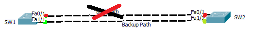
1. Direct Link failure
When main path goes down and backup path is available for that particular destination from source, is called Direct Link Failure. When the main link goes down then next link takes time to be active. So to make backup path immediately active Uplink fast is used in trunk port.switch# spanning-tree uplinkfast
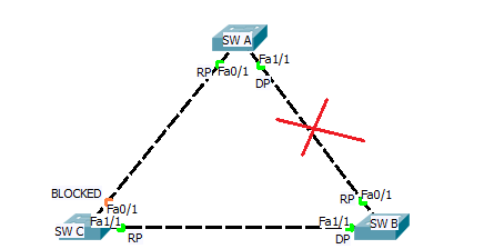
2. Indirect Link Failure
When link between A and B is failed then B says to C that i am Root Brodge and sends BPDU & switch sees that and checks Bridge ID of Switch A and BPDU and sends bridge of of A to B and switc B knows there is a lower bridge in topology. SW C waits for 20 sec before deciding which is max age timer and after 20 sec it start converge the topology. for whole process it takes 52 sec but we can save max age time i.e 20 sec by using backbone fast command.switch# spanning-tree backbone-fast
STP Protection
STP is vulnerable to attack for two reasons:
- STP builds its topology information by accepting a neighboring switch’s BPDU’s.
- The Root Bridge is always determined by the lowest Bridge ID.
Switches with a low priority can be maliciously placed on the network, and elected the Root Bridge. This may result in a suboptimal or unstable STP topology. Cisco implemented three mechanisms to protect the STP topology:
- Root Guard
- BPDU Guard
- BPDU Filtering
All three mechanisms are configured on an individual interface basis, and are disabled by default. When enabled, these mechanisms apply to all VLANs for that particular interface.
1. Root Guard :
Root Guard prevents an unauthorized switch from advertising itself as a Root Bridge.Switch(config)# interface fa0/10
Switch(config-if)# spanning-tree guard root
The above command will prevents the switch from accepting a new Root Bridge off of the fa0/10 interface. If a Root Bridge advertises itself to this port, the port will enter a root-inconsistent state.
2. BPDU Guard :
BPDU Guard is employed on interfaces that are PortFast-enabled. NOrmally a PortFast-enabled interface connects to a host device, and thus the interface should never receive a BPDU. If another switch is accidentally or maliciously connected into a PortFast interface, BPDU Guard will place the interface into an errdisable state. To enable BPDU Guard:Switch(config)# interface fa0/10
Switch(config-if)# spanning-tree bpduguard enable
To take an interface out of an errdisable state, simply disable and re-enable the interface:Switch(config)# interface fa0/10
Switch(config-if)# shutdown
Switch(config-if)# no shutdown
3. BPDU Filter :
BPDU Filtering essentially disables STP on a particular interface, by preventing it from sending or receiving BPDU’s:Switch(config)# interface fa0/10
Switch(config-if)# spanning-tree bpdufilter enable