Ether Channel is a port link aggregation technology developed by Cisco, which provides fault-tolerant high-speed links between Switches, Routers, and Servers. Ether Channel technology allows multiple physical Ethernet links (Fast Ethernet or Gigabit Ethernet) to combine into one logical channel. Ether Channel technology allows grouping of several physical Ethernet links (Fast Ethernet, Gigabit Ethernet, or 10 Gigabit Ethernet) to create one logical Ethernet link for the purpose of providing fault-tolerance and high-speed links between switches, routers and servers.
Ether Channel technology can be used to increase the bandwidth between two devices that support Ether Channel technology and Ether Channel technology provides automatic recovery for the loss of a link by redistributing the load across the remaining links. Ether Channel technology allows automatic redirection of network traffic from the failed link to the remaining links in Ether Channel. An Ether Channel consists of individual Fast Ethernet or Gigabit Ethernet or 10-Gigabit links bundled into a single logical link. The EtherChannel provides full-duplex bandwidth up to 800 Mbps (Fast EtherChannel FEC) or 8 Gbps (Gigabit EtherChannel) or 10 Gbps (10-Gigabit Etherchannel 10 GEC) between Switches, Routers and Servers.
The main advantages of Ether Channel technology is that it allows load sharing of traffic among the links in the channel as well as redundancy in the event that one or more links in the Ether Channel fail.
Configuring Layer 2 Ether Channel
Two neighboring switches can treat multiple parallel links between each other as a single logical link called an Ether Channel. Without Ether Channel, a switch treats each physical port as an independent port, applying MAC learning, forwarding, and STP logic per physical port. With Ether Channel, the switch applies all those same processes to a group of physical ports as one entity: the Ether Channel. Without Ether Channel, with parallel links between two switches, STP/RSTP would block all links except one, but with Ether Channel, the switch can use all the links, load balancing the traffic over the links.
Ether Channel may be one of the most challenging switch features to make work. First, the configuration has several options, so you have to remember the details of which options work together. Second, the switches also require a variety of other interface settings to match among all the links in the channel, so you have to know those settings as well.
Configuring a Manual Layer 2 Ether Channel
To configure a Layer 2 Ether Channel so that all the ports always attempt to be part of the channel, simply add the correct channel-group configuration command to each physical interface, on each switch, all with the on keyword, and all with the same number. The on keyword tells the switches to place a physical interface into an Ether Channel, and the number identifies the Port Channel interface number that the interface should be a part of.
Before getting into the configuration and verification, however, you need to start using three terms as synonyms: Ether Channel, PortChannel, and Channel-group. Oddly, IOS uses the channel-group configuration command, but then to display its status, IOS uses the show etherchannel command. Then the output of this show command refers to neither an “EtherChannel” nor a “Channel-group,” instead using the term “PortChannel.” So, pay close attention to these three terms in the example.
To configure an EtherChannel manually, follow these steps:
Step 1. Add the channel-group number mode on command in interface configuration mode under each physical interface that should be in the channel to add it to the channel.
Step 2. Use the same number for all commands on the same switch, but the channelgroup number on the neighboring switch can differ.
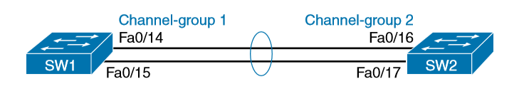
Below shows a simple example, with two links between switches SW1 and SW2. The configuration shows SW1’s two interfaces placed into channelgroup 1, with two show commands to follow.
SW1# configure terminal
SW1(config)# interface fa 0/14
SW1(config-if)# channel-group 1 mode on
SW1(config)# interface fa 0/15
SW1(config-if)# channel-group 1 mode on
SW1(config-if)# ^Z
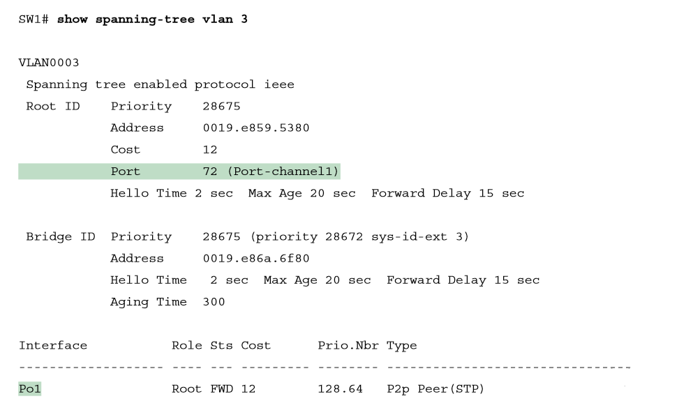
Take a few moments to look at the output in the two show commands in the example, as well. First, the show spanning-tree command lists Po1, short for PortChannel1, as an interface. This interface exists because of the channel-group commands using the 1 parameter. STP no longer operates on physical interfaces Fa0/14 and Fa0/15, instead operating on the Port Channel1 interface, so only that interface is listed in the output. Next, note the output of the show etherchannel 1 summary command. It lists as a heading “Port-channel,” with Po1 below it. It also lists both Fa0/14 and Fa0/15 in the list of ports, with a (P) beside each. Per the legend, the P means that the ports are bundled in the port channel, which is a code that means these ports have passed all the configuration checks and are valid to be included in the channel.
Configuring Dynamic EtherChannels
In addition to manual configuration, Cisco switches also support two different configuration options that then use a dynamic protocol to negotiate whether a particular link becomes part of an Ether Channel or not. Basically, the configuration enables a protocol for a particular channel-group number. At that point, the switch can use the protocol to send messages to/from the neighboring switch and discover whether their configuration settings pass all checks. If a given physical link passes, the link is added to the EtherChannel and used; if not, it is placed in a down state, and not used, until the configuration inconsistency can be resolved.
Most Cisco Catalyst switches support the Cisco-proprietary Port Aggregation Protocol (PAgP) and the IEEE standard Link Aggregation Control Protocol (LACP), based on IEEE standard 802.3ad. Although differences exist between the two, to the depth discussed here, they both accomplish the same task: negotiate so that only links that pass the configuration checks are actually used in an Ether Channel.
One difference of note is that LACP does support more links in a channel—16—as compared to PaGP’s maximum of 8. With LACP, only 8 can be active at one time, with the others waiting to be used should any of the other links fail.
To configure either protocol, a switch uses the channel-group configuration commands on each switch, but with a keyword that either means “use this protocol and begin negotiations” or “use this protocol and wait for the other switch to begin negotiations.” As shown in Figure, the desirable and auto keywords enable PAgP, and the active and passive keywords enable LACP. With these options, at least one side has to begin the negotiations. In other words, with PAgP, at least one of the two sides must use desirable, and with LACP, at least one of the two sides must use active.

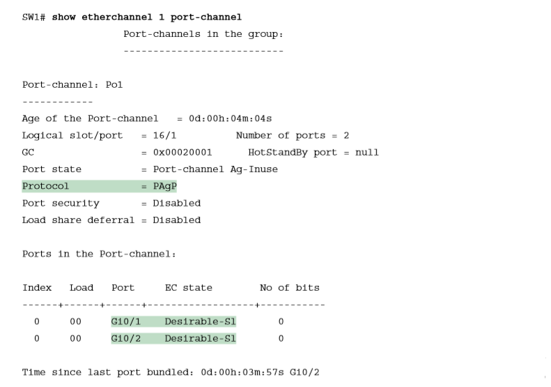
Do not use the on parameter on one end, and either auto or desirable (or for LACP, active or passive) on the neighboring switch. The on option uses neither PAgP nor LACP, so a configuration that uses on, with PAgP or LACP options on the other end, would prevent the EtherChannel from working. Below shows the verification of that configuration, with the command show etherchannel 1 port-channel. This command confirms the protocol in use (PAgP, because the desirable keyword was configured), and the list of interfaces in the channel.
Physical Interface Configuration and EtherChannels
Even when the channel-group commands have all been configured correctly, other configuration settings can prevent a switch from using a physical port in an EtherChannel—even physical ports manually configured to be part of the channel First, before using a physical port in an EtherChannel, the switch compares the new physical port’s configuration to the existing ports in the channel. That new physical interface’s settings must be the same as the existing ports’ settings; otherwise, the switch does not add the new link to the list of approved and working interfaces in the channel. That is, the physical interface remains configured as part of the PortChannel, but it is not used as part of the channel, often being placed into some nonworking state.
The list of items the switch checks includes the following:
- Speed
- Duplex
- Operational access or trunking state (all must be access, or all must be trunks)
- If an access port, the access VLAN
- If a trunk port, the allowed VLAN list (per the switchport trunk allowed command)
- If a trunk port, the native VLAN
- STP interface settings
Ether Channel Mis-Configuration guard
Port-channel or logical interface has a Mac address and while sending Data it uses single MAc address of Logical interface which can be any single physical interface MAC address. In cisco it is default enabled.
While configuring port-channel, if one switch is configured ether channel and another is not, Switch 1 will send all control plain traffic with same Mac and it will think that it will receive all traffic with same MAc address but in switch 2 no ether channel is configured so switch 1 will receive with different MAc address. So, while happening this Switch1 will put it’same alll port into Error-disalbe mode. So, it is preferred to be configured etherchannel after shutdown neighbour’s interface.
EtherChannel Load Distribution
When using Layer 2 EtherChannels, a switch’s MAC learning process associates MAC addresses with the PortChannel interfaces and not the underlying physical ports. Later, when a switch makes a forwarding decision to send a frame out a PortChannel interface, the switch must do more work: to decide out which specific physical port to use to forward the frame. IOS documentation refers to those rules as EtherChannel load distribution or load balancing.
EtherChannel load distribution makes the choice for each frame based on various numeric values found in the Layer 2, 3, and 4 headers. The process uses one configurable setting as input: the load distribution method as defined with the port-channel load-balance method global command. The process then performs some match against the fields identified by the configured method.
Below lists the most common methods. However, note that some switches may support only MAC-based methods, or only MAC- and IP-based methods, depending on the model and software version.

To appreciate why you might want to use different methods, you need to consider the results of how switches make their choice. (The discussion here focuses on the result, and not the logic, because the logic remains internal to the switch, and Cisco does not document how each switch model or IOS version works internally.) However, the various load distribution algorithms do share some common goals:
■ To cause all messages in a single application flow to use the same link in the channel, rather than being sent over different links. Doing so means that the switch will not inadvertently reorder the messages sent in that application flow by sending one message over a busy link that has a queue of waiting messages, while immediately sending the next message out an unused link.
■ To integrate the load distribution algorithm work into the hardware forwarding ASIC so that load distribution works just as quickly as the work to forward any other frame.
■ To use all the active links in the EtherChannel, adjusting to the addition and removal of active links over time.
■ Within the constraints of the other goals, balance the traffic across those active links.
In short, the algorithms first intend to avoid message reordering, make use of the switch forwarding ASICs, and use all the active links. However, the algorithm does not attempt to send the exact same number of bits over each link over time. The algorithm does try to balance the traffic, but always within the constraints of the other goals.
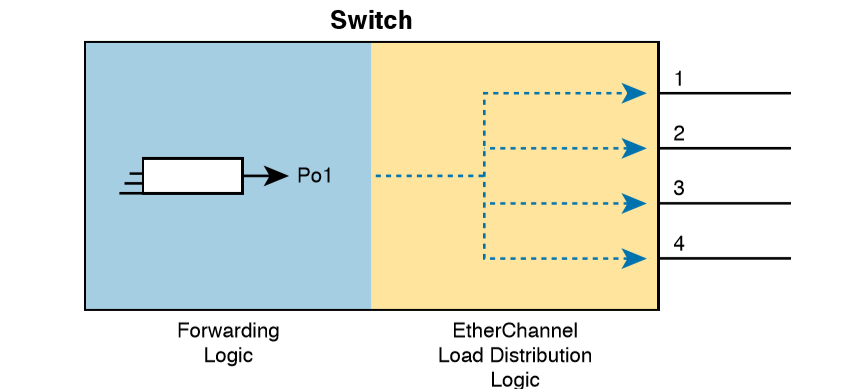
Whatever load distribution method you choose, the method identifies fields in the message headers. Any messages in the same application flow will then have the same values in the fields used by the load distribution algorithm and will always be forwarded over the same link. For example, when a user connects to a website, that web server may return thousands of packets to the client. Those thousands of packets should flow over the same link in the Ether Channel. For instance, with the load distribution method of src-mac (meaning source MAC address), all frames with the same MAC address flow over one link. Figure shows the idea with pseudo MAC addresses, with the load distribution sending frames with source MAC 1 over link 1, source MAC 2 over link 2, and source MAC 3 over link 3.

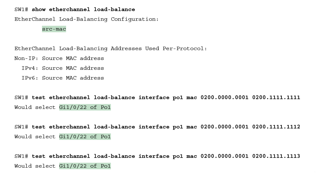
Below output shows how switch SW1 distributes traffic when using src-mac load distribution. The example lists the output from three of the test etherchannel load-balance commands, but note that all three commands use the same source MAC address. As a result, the answer from each command references the same interface (G1/0/22 in this case)
The Effects of the Ether Channel Load Distribution Algorithm
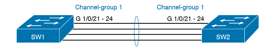
Below details a new Ether Channel that will be used in two examples to show the effects of load distribution. The examples will focus on frames sent by switch SW1 in the figure, showing the use of the test etherchannel load-balance EXEC command. That command asks the switch to consider some addresses or ports and answer the question: which link would you use when forwarding a message with those address/port values?
Above output example makes two important points:
- All three tests list the same outgoing physical interface because (1) the method uses only the source MAC address, and (2) all three tests use the same MAC addresses.
- All three tests use a different destination MAC address, with different low-order bits, but that had no impact on the choice because the method—src-mac—does not consider the destination MAC address.
Configuring Layer 3 Ether Channel
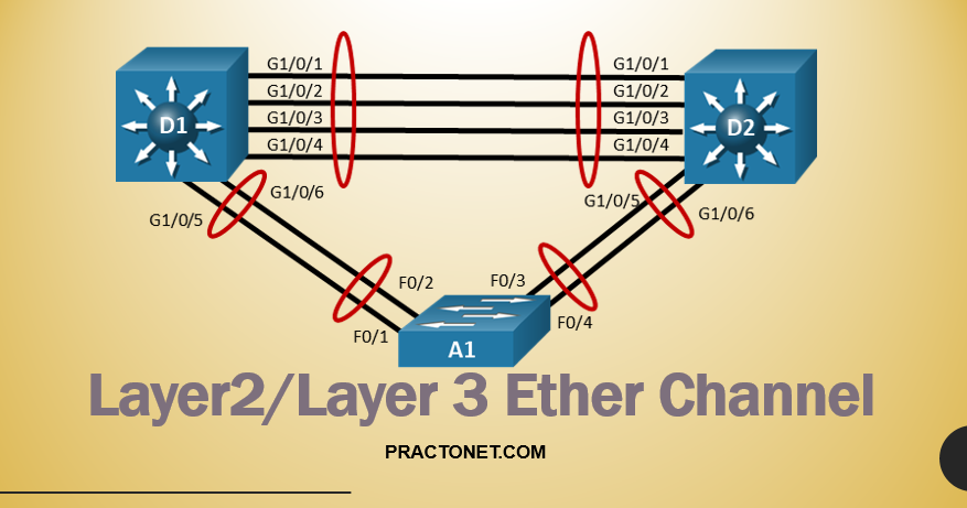
As we know that routed interfaces can be used with a single point-to-point link between pairs of Layer 3 switches, or between a Layer 3 switch and a router. However, in most designs, the network engineers use at least two links between each pair of distribution and core switches, as shown in Figure.
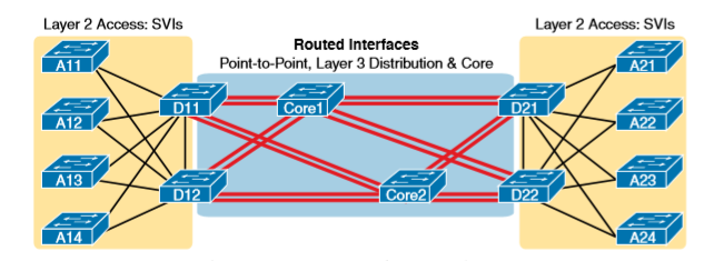
While each individual port in the distribution and core could be treated as a separate routed port, it is better to combine each pair of parallel links into a Layer 3 Ether Channel. Without using Ether Channel, you can still make each port on each switch in the center of the figure be a routed port. It works. However, once you enable a routing protocol but don’t use Ether Channels, each Layer 3 switch will now learn two IP routes with the same neighboring switch as the next hop—one route over one link, another route over the other link.
Using a Layer 3 EtherChannel makes more sense with multiple parallel links between two switches. By doing so, each pair of links acts as one Layer 3 link. So, each pair of switches has one routing protocol neighbor relationship with the neighbor, and not two. Each switch learns one route per destination per pair of links, and not two. IOS then balances the traffic, often with better balancing than the balancing that occurs with the use of multiple IP routes to the same subnet. Overall, the Layer 3 EtherChannel approach works much better than leaving each link as a separate routed port and using Layer 3 balancing.
Compared to what you have already learned, configuring a Layer 3 Ether Channel takes only a little more work. The following checklist shows the steps, assuming a static definition.
Step 1. Configure the physical interfaces as follows, in interface configuration mode:
- Add the channel-group number mode on command to add it to the channel. Use the same number for all physical interfaces on the same switch, but the number used (the channel-group number) can differ on the two neighboring switches.
- Add the no switchport command to make each physical port a routed port.
Step 2. Configure the PortChannel interface:
- Add the no switchport command to make sure that the port-channel interface acts as a routed port. (IOS may have already added this command.)
- Use the ip address address mask command to configure the address and mask.
Example shows the configuration for a Layer 3 EtherChannel for switch SW1 in Figure. The EtherChannel defines port-channel interface 12 and uses subnet 10.1.12.0/24.
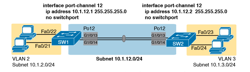
Layer 3 EtherChannel Configuration on Switch SW1
interface GigabitEthernet1/0/13
no switchport
no ip address
channel-group 12 mode on
!

interface GigabitEthernet1/0/14
no switchport
no ip address
channel-group 12 mode on
!

interface Port-channel12
no switchport
ip address 10.1.12.1 255.255.255.0
Of particular importance, note that although the physical interfaces and PortChannel interface are all routed ports, the IP address should be placed on the PortChannel interface only. In fact, when the no switchport command is configured on an interface, IOS adds the no ip address command to the interface. Then configure the IP address on the Port Channel interface only.
Once configured, the PortChannel interface appears in several commands, as shown below. The commands that list IP addresses and routes refer to the PortChannel interface. Also, note that the show interfaces status command lists the fact that the physical ports and the port-channel 12 interface are all routed ports.

For a final bit of verification, you can examine the EtherChannel directly with the show etherchannel summary command. Note in particular that it lists a flag legend for characters that identify key operational states, such as whether a port is bundled (included) in the PortChannel (P) and whether it is acting as a routed (R) or switched (S) port.
Troubleshooting Layer 3 Ether Channels
When you are troubleshooting a Layer 3 EtherChannel, there are two main areas to consider. First, you need to look at the configuration of the channel-group command, which enables an interface for an EtherChannel. Second, you should check a list of settings that must match on the interfaces for a Layer 3 EtherChannel to work correctly. As for the channel-group interface subcommand, this command can enable EtherChannel statically or dynamically. If dynamic, this command’s keywords imply either Port Aggregation Protocol (PaGP) or Link Aggregation Control Protocol (LACP) as the protocol to negotiate between the neighboring switches whether they put the link into the Ether Channel.
Additionally, you must do more than just configure the channel-group command correctly for all the physical ports to be bundled into the EtherChannel. Layer 2 EtherChannels have a longer list of requirements, but Layer 3 EtherChannels also require a few consistency checks between the ports before they can be added to the EtherChannel. The following is the list of requirements for Layer 3 EtherChannels:
no switchport: The PortChannel interface must be configured with the no switchport command, and so must the physical interfaces. If a physical interface is not also configured with the no switchport command, it will not become operational in the EtherChannel.
Speed: The physical ports in the channel must use the same speed.
duplex: The physical ports in the channel must use the same duplex