Networking devices forward data in the form of messages, typically data-link frames like Ethernet frames. Network programmability and Software Defined Networking (SDN) take those ideas, analyze the pieces, find ways to improve them for today’s needs, and reassemble those ideas into a new way of making networks work. At the end of that rearrangement, the devices in the network still forward messages, but the how and why have changed.
The Data, Control, and Management Planes
Many ideas should come to mind. For instance, routers and switches physically connect to each other with cables, and with wireless, to create networks. They forward messages: switches forward Ethernet frames, and routers forward packets. They use many different protocols to learn useful information such as routing protocols for learning network layer routes. Everything that networking devices do can be categorized as being in a particular plane.
The Data Plane
The term data plane refers to the tasks that a networking device does to forward a message. In other words, anything to do with receiving data, processing it, and forwarding that same data—whether you call the data a frame, a packet, or, more generically, a message—is part of the data plane. For example, think about how routers forward IP packets, as shown in Figure. If you focus on the Layer 3 logic for a moment, the host sends the (step 1) to its default router, R1. R1 does some processing on the received packet, makes a forwarding (routing) decision, and forwards the packet (step 2). Routers R3 and R4 also receive, process, and forward the packet (steps 3 and 4).

Now broaden your thinking for a moment and try to think of everything a router or switch might do when receiving, processing, and forwarding a message. Of course, the forwarding decision is part of the logic; in fact, the data plane is often called the forwarding plane. But think beyond matching the destination address to a table. For perspective, the following list details some of the more common actions that a networking device does that fit into\ the data plane:
- De-encapsulating and re-encapsulating a packet in a data-link frame (routers, Layer 3 switches)
- Adding or removing an 802.1Q trunking header (routers and switches)
- Matching an Ethernet frame’s destination Media Access Control (MAC) address to the MAC address table (Layer 2 switches)
- Matching an IP packet’s destination IP address to the IP routing table (routers, Layer 3 switches)
- Encrypting the data and adding a new IP header (for virtual private network [VPN] processing)
- Changing the source or destination IP address (for Network Address Translation [NAT] processing)
- Discarding a message due to a filter (access control lists [ACLs], port security)
The Control Plane
Next, take a moment to ponder the kinds of information that the data plane needs to know beforehand so that it can work properly. For instance, routers need IP routes in a routing table before the data plane can forward packets. Layer 2 switches need entries in a MAC address table before they can forward Ethernet frames out the one best port to reach the destination. Switches must use Spanning Tree Protocol (STP) to limit which interfaces can be used for forwarding so that the data plane works well and does not loop frames forever.
From one perspective, the information supplied to the data plane controls what the data plane does. For instance, a router needs a route that matches a packet’s destination address for the router to know how to route (forward) the packet. When a router’s data plane tries to match the routing table and finds no matching route, the router discards the packet. And what controls the contents of the routing table? Various control plane processes. The term control plane refers to any action that controls the data plane. Most of these actions have to do with creating the tables used by the data plane, tables like the IP routing table, an IP Address Resolution Protocol (ARP) table, a switch MAC address table, and so on. By adding to, removing, and changing entries to the tables used by the data plane, the control plane processes control what the data plane does. You already know about many control plane protocols—for instance, all the IP routing protocols.
Traditional networks use both a distributed data plane and a distributed control plane. In other words, each device has a data plane and a control plane, and the network distributes those functions into each individual device, as shown in the example.

In the figure, Open Shortest Path First (OSPF), the control plane protocol, runs on each router (that is, it is distributed among all the routers). OSPF on each router then adds to, removes from, and changes the IP routing table on each router. Once populated with useful routes, the data plane’s IP routing table on each router can forward incoming packets, as shown from left to right across the bottom of the figure. The following list includes many of the more common control plane protocols:
- Routing protocols (OSPF, Enhanced Interior Gateway Routing Protocol [EIGRP], Routing Information Protocol [RIP], Border Gateway Protocol [BGP])
- IPv4 ARP
- IPv6 Neighbor Discovery Protocol (NDP)
- Switch MAC learning
- STP
Without the protocols and activities of the control plane, the data plane of traditional networking devices would not function well. Routers would be mostly useless without routes learned by a routing protocol. Without learning MAC table entries, a switch could still forward unicasts by flooding them, but doing that for all frames would create much more load on the local-area network (LAN) compared to normal switch operations. So the data plane must rely on the control plane to provide useful information.
The Management Plane
The control plane performs overhead tasks that directly impact the behavior of the data plane. The management plane performs overhead work as well, but that work does not directly impact the data plane. Instead, the management plane includes protocols that allow network engineers to manage the devices. Telnet and Secure Shell (SSH) are two of the most obvious management plane protocols. To emphasize the difference with control plane protocols, think about two routers: one configured to allow Telnet and SSH into the router and one that does not. Both could still be running a routing protocol and routing packets, whether or not they support Telnet and SSH.

Examples of Network Programmability and SDN
Here we will introduces three different SDN and network programmability solutions available from Cisco. Others exist as well. These three were chosen because they give a wide range of comparison points:
- OpenDaylight Controller
- Cisco Application Centric Infrastructure (ACI)
- Cisco APIC Enterprise Module (APIC-EM)
OpenDaylight and OpenFlow
One common form of SDN comes from the Open Networking Foundation (ONF) and is billed as Open SDN. The ONF (www.opennetworking.org) acts as a consortium of users (operators) and vendors to help establish SDN in the marketplace. Part of that work defines protocols, SBIs, NBIs, and anything that helps people implement their vision of SDN.
The ONF model of SDN features OpenFlow. OpenFlow defines the concept of a controller along with an IP-based SBI between the controller and the network devices. Just as important, OpenFlow defines a standard idea of what a switch’s capabilities are, based on the ASICs and TCAMs commonly used in switches today. (That standardized idea of what a switch does is called a switch abstraction.) An OpenFlow switch can act as a Layer 2 switch, a Layer 3 switch, or in different ways and with great flexibility beyond the traditional model of a Layer 2/3 switch. The Open SDN model centralizes most control plane functions, with control of the network done by the controller plus any applications that use the controller’s NBIs.
In the OpenFlow model, applications may use any APIs (NBIs) supported on the controller platform to dictate what kinds of forwarding table entries are placed into the devices; however, it calls for OpenFlow as the SBI protocol. Additionally, the networking devices need to be switches that support OpenFlow. Because the ONF’s Open SDN model has this common thread of a controller with an OpenFlow SBI, the controller plays a big role in the network.
The OpenDaylight Controller
First, if you were to look back at the history of OpenFlow, you could find information on dozens of different SDN controllers that support the OpenFlow SDN model. Some were more research oriented, during the years in which SDN was being developed and was more of an experimental idea. As time passed, more and more vendors began building their own controllers. And those controllers often had many similar features, because they were trying to accomplish many of the same goals. As you might expect, some consolidation eventually needed to happen.
The OpenDaylight open-source SDN controller is one of the more successful SDN controller platforms to emerge from the consolidation process over the 2010s. OpenDaylight took many of the same open-source principles used with Linux, with the idea that if enough vendors worked together on a common open-source controller, then all would benefit. All those vendors could then use the open-source controller as the basis for their own products, with each vendor focusing on the product differentiation part of the effort, rather than the fundamental features. The result was that back in the mid-2010s, the OpenDaylight SDN controller (www.opendaylight.org) was born. OpenDaylight (ODL) began as a separate project but now exists as a project managed by the Linux Foundation.
Figure shows a generalized version of the ODL architecture. In particular, note the variety of SBIs listed in the lower part of the controller box: OpenFlow, NetConf, PCEP, BGP-LS, and OVSDB; many more exist. The ODL project has enough participants so that it includes a large variety of options, including multiple SBIs, not just OpenFlow. ODL has many features, with many SBIs, and many core features. A vendor can then take ODL, use the parts that make sense for that vendor, add to it, and create a commercial ODL controller.

Cisco Application Centric Infrastructure (ACI)
Interestingly, many SDN offerings began with research that discarded many of the old networking paradigms in an attempt to create something new and better. For instance, OpenFlow came to be from the Stanford University Clean Slate research project that had researchers reimagining (among other things) device architectures. Cisco took a similar research path, but Cisco’s work happened to arise from different groups, each focused on different parts of the network: data center, campus, and WAN. That research resulted in Cisco’s current SDN offerings of ACI in the data center, Software-Defined Access (SDA) in the enterprise campus, and Software-Defined WAN (SD-WAN) in the enterprise WAN.
When reimagining networking for the data center, the designers of SCI focused on the applications that run in a data center and what they need. As a result, they built networking concepts around application architectures. Cisco made the network infrastructure become application centric, hence the name of the Cisco data center SDN solution: Application Centric Infrastructure, or ACI. ACI set about to create data center networking with the flexibility and automation built into the operational model. Old data center networking models with a lot of per-physicalinterface configuration on switches and routers were just poor models for the rapid pace of change and automated nature of modern data centers. This section looks at some of the detail of ACI to give you a sense of how ACI creates a powerful and flexible network to support a modern data center in which VMs and containers are created, run, move, and are stopped dynamically as a matter of routine.
ACI Physical Design: Spine and Leaf
The Cisco ACI uses a specific physical switch topology called spine and leaf. While the other parts of a network might need to allow for many different physical topologies, the data center could be made standard and consistent. But what particular standard and consistent topology? Cisco decided on the spine and leaf design, also called a Clos network after one of its creators. With ACI, the physical network has a number of spine switches and a number of leaf switches. The figure shows the links between switches, which can be single links or multiple parallel links. Of note in this design (assuming a single-site design):
- Each leaf switch must connect to every spine switch.
- Each spine switch must connect to every leaf switch.
- Leaf switches cannot connect to each other.
- Spine switches cannot connect to each other.
- Endpoints connect only to the leaf switches.
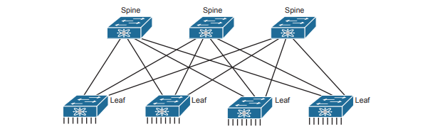
Endpoints connect only to leaf switches and never to spine switches. None of the endpoints connect to the spine switches; they connect only to the leaf switches. The endpoints can be connections to devices outside the data center, like the router on the left. By volume, most of the endpoints will be either physical servers running a native OS or servers running virtualization software with numbers of VMs and containers as shown in the center of the figure. Also, note that the figure shows a typical design with multiple leaf switches connecting to a single hardware endpoint like a Cisco Unified Computing System (UCS) server. Depending on the design requirements, each UCS might connect to at least two leaf switches, both for redundancy and for greater capacity to support the VMs and containers running on the UCS hardware. (In fact, in a small design with UCS or similar server hardware, every UCS might connect to every leaf switch.)

ACI Operating Model with Intent-Based Networking
The model that Cisco defines for ACI uses a concept of endpoints and policies. The endpoints are the VMs, containers, or even traditional servers with the OS running directly on the hardware. ACI then uses several constructs as implemented via the Application Policy Infrastructure Controller (APIC), the software that serves as the centralized controller for ACI. Consider the application architecture of a typical enterprise web app for a moment. Most casual observers think of a web application as one entity, but one web app often exists as three separate servers:
- Web server: Users from outside the data center connect to a web server, which sends web page content to the user.
- App (Application) server: Because most web pages contain dynamic content, the app server does the processing to build the next web page for that particular user based on the user’s profile and latest actions and input.
- DB (Database) server: Many of the app server’s actions require data; the DB server retrieves and stores the data as requested by the app server.
To accommodate those ideas, ACI uses an intent-based networking (IBN) model . With that model, the engineer, or some automation program, defines the policies and intent for which endpoints should be allowed to communicate and which should not. Then the controller determines what that means for this network at this moment in time, depending on where the endpoints are right now. For instance, when starting the VMs for this app, the virtualization software would create (via the APIC) several endpoint groups (EPGs). The controller must also be told the access policies, which define which EPGs should be able to communicate (and which should not), as implied in the figure with arrowed lines. For example, the routers that connect to the network external to the data center should be able to send packets to all web servers, but not to the app servers or DB servers.

Note that at no point did the previous paragraph talk about which physical switch interfaces should be assigned to which VLAN, or which ports are in an EtherChannel; the discussion moves to an application-centric view of what happens in the network. Once all the endpoints, policies, and related details are defined, the controller can then direct the network as to what needs to be in the forwarding tables to make it all happen—and to more easily react when the VMs start, stop, or move.
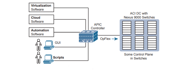
To make it all work, ACI uses a centralized controller called the Application Policy Infrastructure Controller (APIC). The name defines the function in this case: it is the controller that creates application policies for the data center infrastructure. The APIC takes the intent (EPGs, policies, and so on), which completely changes the operational model away from configuring VLANs, trunks, EtherChannels, ACLs, and so on.

The APIC, of course, has a convenient GUI, but the power comes in software control—that is, network programmability. The same virtualization software, or cloud or automation software, even scripts written by the network engineer, can define the endpoint groups, policies, and so on to the APIC. But all these players access the ACI system by interfacing to the APIC. the network engineer no longer needs to connect to each individual switch and configure CLI commands.
Cisco APIC Enterprise Module
The next example of a Cisco SDN solution in this section, called APIC Enterprise Module (APIC-EM), solves a different problem. When Cisco began to reimagine networking in the enterprise, they saw a huge barrier: the installed base of their own products in most of their customer’s networks. Any enterprise SDN solution that used new SBIs—SBIs that only some of the existing devices and software levels supported—would create a huge barrier to adoption.
APIC-EM Basics
APIC-EM assumes the use of the same traditional switches and routers with their familiar distributed data and control planes. Cisco rejected the idea that its initial enterprise-wide SDN (network programmability) solution could begin by requiring customers to replace all hardware. Instead, Cisco looked for ways to add the benefits of network programmability with a centralized controller while keeping the same traditional switches and routers in place. That approach could certainly change over time (and it has), but Cisco APIC-EM does just that: offer enterprise SDN using the same switches and routers already installed in networks.
What advantages can a controller-based architecture bring if the devices in the network have no new features? In short, adding a centralized controller does nothing in comparison with old network management offerings. Adding a centralized controller with powerful northbound APIs opens many possibilities for customers/operators, while also creating a world in which Cisco and its partners can bring new and interesting management applications to market. It includes these applications:
- Topology map: The application discovers and displays the topology of the network.
- Path Trace: The user supplies a source and destination device, and the application shows the path through the network, along with details about the forwarding decision at each step.
- Plug and Play: This application provides Day 0 installation support so that you can unbox a new device and make it IP reachable through automation in the controller.
- Easy QoS: With a few simple decisions at the controller, you can configure complex QoS features at each device.

APIC-EM does not directly program the data or control planes, but it does interact with the management plane via Telnet, SSH, and/or SNMP; consequently, it can indirectly impact the data and control planes. The APIC-EM controller does not program flows into tables or ask the control plane in the devices to change how it operates. But it can interrogate and learn the configuration state and operational state of each device, and it can reconfigure each device, therefore changing how the distributed control and data plane operates.