New approaches to networking emerged in the 2010s, approaches that change where some of the control plane functions occur. Many of those approaches move parts of the control plane work into software that runs as a centralized application called a controller.
Controllers and Centralized Control
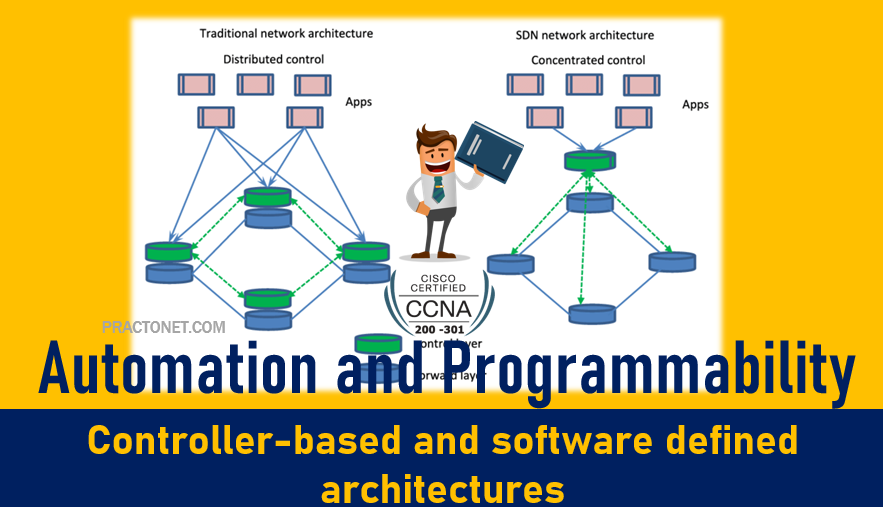
Most traditional control plane processes use a distributed architecture. For example, each router runs its own OSPF routing protocol process. To do their work, those distributed control plane processes use messages to communicate with each other, like OSPF protocol messages between routers. As a result, traditional networks are said to use a distributed control plane. The people who created today’s control plane concepts, like STP, OSPF, EIGRP, and so on, could have chosen to use a centralized control plane. That is, they could have put the logic in one place, running on one device, or on a server. Then the centralized software could have used protocol messages to learn information from the devices, but with all the processing of the information at a centralized location. But they instead chose a distributed architecture.
There are pros and cons to using distributed and centralized architectures to do any function in a network. Many control plane functions have a long history of working well with a distributed architecture. However, a centralized application can be easier to write than a distributed application, because the centralized application has all the data gathered into one place. And this emerging world of software-defined architectures often uses a centralized architecture, with a centralized control plane, with its foundations in a service called a controller.
A controller, or SDN controller, centralizes the control of the networking devices. The degree of control, and the type of control, varies widely. For instance, the controller can perform all control plane functions, replacing the devices’ distributed control plane. Alternately, the controller can simply be aware of the ongoing work of the distributed data, control, and management planes on the devices, without changing how those operate. And the list goes on, with many variations.
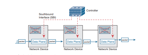
To better understand the idea of a controller, consider one specific case as shown in Figure , in which one SDN controller centralizes all important control plane functions. First, the controller sits anywhere in the network that has IP reachability to the devices in the network. Each of the network devices still has a data plane; however, note that none of the devices has a control plane. In the variation of SDN as shown in Figure, the controller directly programs the data plane entries into each device’s tables. The networking devices do not populate their forwarding tables with traditional distributed control plane processes.
The Southbound Interface
In a controller-based network architecture, the controller needs to communicate to the networking devices. In most network drawings and architecture drawings, those network devices typically sit below the controller. There is an interface between the controller and those devices, and given its location at the bottom part of drawings, the interface came to be known as the southbound interface, or SBI.
Several different options exist for the SBI. The overall goal is network programmability, so the interface moves away from being only a protocol. An SBI often includes a protocol, so that the controller and devices can communicate, but it often includes an application programming interface (API). An API is a method for one application (program) to exchange data with another application. Rearranging the words to describe the idea, an API is an interface to an application program. Programs process data, so an API lets two programs exchange data. While a protocol exists as a document, often from a standards body, an API often exists as usable code—functions, variables, and data structures—that can be used by one program to communicate and copy structured data between the programs across a network.
So, back to the term SBI: it is an interface between a program (the controller) and a program (on the networking device) that lets the two programs communicate, with one goal being to allow the controller to program the data plane forwarding tables of the networking device. Unsurprisingly, in a network architecture meant to enable network programmability, the capabilities of the SBIs and their APIs tell us a lot about what that particular architecture can and cannot do. For instance, some controllers might support one or a few SBIs, for a specific purpose, while others might support many more SBIs, allowing a choice of SBIs to use. The comparisons of SBIs go far beyond this chapter, but it does help to think about a few; the second major section gives three sample architectures that happen to show three separate SBIs, specifically:
- OpenFlow (from the ONF; www.opennetworking.org)
- OpFlex (fromCisco; used with ACI)
- CLI (Telnet/SSH) and SNMP (used with Cisco APIC-EM)
- CLI (Telnet/SSH) and SNMP, and NETCONF (used with Cisco Software-Defined Access)
The Northbound Interface
Think about the programming required at the controller. How does the controller know what to add? How does it choose? What kind of information would your program need to gather before it could attempt to add something like MAC table entries or IP routes to a network? You might think of these
- A list of all the devices in the network
- The capabilities of each devices
- The interfaces/ports on each device
- The current state of each port
- The topology—which devices connect to which, over which interfaces
- Device configuration—IP addresses, VLANs, and so on as configured on the devices
A controller does much of the work needed for the control plane in a centralized control model. It gathers all sorts of useful information about the network, like the items in the previous list. The controller itself can create a centralized repository of all this useful information about the network. A controller’s northbound interface (NBI) opens the controller so its data and functions can be used by other programs, enabling network programmability, with much quicker development. Programs can pull information from the controller, using the controller’s APIs. The NBIs also enable programs to use the controller’s capabilities to program flows into the devices using the controller’s SBIs.
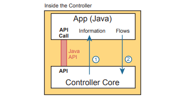
To see where the NBI resides, first think about the controller itself. The controller is software, running on some server, which can be a VM or a physical server. An application can run on the same server as the controller and use an NBI, which is an API, so that two programs can communicate. Figure below shows just such an example. The big box in the figure represents the system where the controller software resides. This particular controller happens to be written in Java and has a Java-based native API. Anyone—the same vendor as the controller vendor, another company, or even you—can write an app that runs on this same operating system that uses the controller’s Java API. By using that API to exchange data with the controller, the application can learn information about the network. The application can also program flows in the network—that is, ask the controller to add the specific match/action logic (flows) into the forwarding tables of the networking devices.
SDA Fabric, Underlay, and Overlay
SDA uses the software-defined architectural mode, with a controller and various APIs. It still uses a physical network with switches and routers, cables, and various endpoints. At the center sits the Digital Network Architecture (DNA) Center controller, with human users making use of a graphical user interface (GUI) and automation using APIs. In short, DNA Center is the controller for SDA networks. Architecturally, the southbound side of the controller contains the fabric, underlay, and overlay. By design in SDN implementations, most of the interesting new capabilities occur on the northbound side.
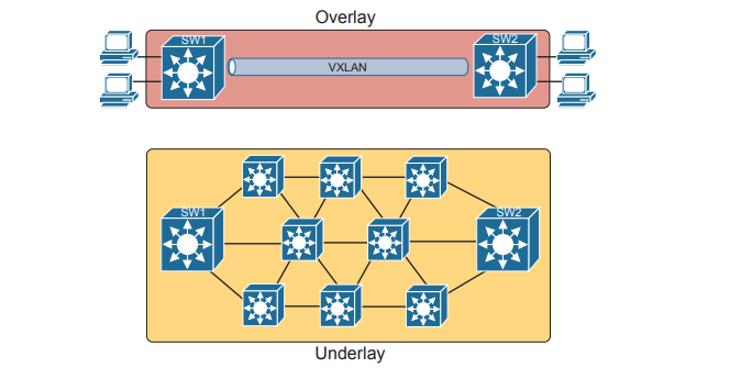
Overlay: The mechanisms to create VXLAN tunnels between SDA switches, which are then used to transport traffic from one fabric endpoint to another over the fabric.
Underlay: The network of devices and connections (cables and wireless) to provide IP connectivity to all nodes in the fabric, with a goal to support the dynamic discovery of all SDA devices and endpoints as a part of the process to create overlay VXLAN tunnels.
Fabric: The combination of overlay and underlay, which together provide all features to deliver data across the network with the desired features and attributes.
For instance, think about the idea of sending packets from hosts on the left of a network, over SDA, to hosts on the right. For instance, imagine a packet enters on the left side of the physical network at the bottom of Figure and eventually exits the campus out switch SW2 on the far right. This underlay network looks like a more traditional network drawing, with several devices and links.
The SDA Underlay
With SDA, the underlay exists to provide connectivity between the nodes in the SDA environment for the purpose of supporting VXLAN tunnels in the overlay network. To do that, the underlay includes the switches, routers, cables, and wireless links used to create the physical network. It also includes the configuration and operation of the underlay so it can support the work of the overlay network.
Using Existing Gear for the SDA Underlay
To build an SDA underlay network , companies have two basic choices. They can use their existing campus network and add new configuration to create an underlay network, while still supporting their existing production traffic with traditional routing and switching. Alternately, the company can purchase some new switches and build the SDA network without concern for harming existing traffic, and migrate endpoints to the new SDA network over time. To build SDA into an existing network, it helps to think for a moment about some typical campus network designs. The larger campus site may use either a two-tier or three-tier design. It has a cluster of wireless LAN controllers (WLCs) to support a number of lightweight APs (LWAPs). Engineers have configured VLANs, VLAN trunks, IP routing, IP routing protocols, ACLs, and so on. And the LAN connects to WAN routers.
SDA can be added into an existing campus LAN, but doing so has some risks and restrictions. First and foremost, you have to be careful not to disrupt the current network while adding the new SDA features to the network. The issues include:
- Because of the possibility of harming the existing production configuration, DNA Center should not be used to configure the underlay if the devices are currently used in production. (DNA Center will be used to configure the underlay with deployments that use all new hardware.)
- The existing hardware must be from the SDA compatibility list, with different models supported depending on their different SDA roles (see a link at www.cisco.com/go/sda).
- The device software levels must meet the requirements, based on their roles, as detailed in that same compatibility list.
The SDA underlay configuration requires you to think about and choose the different SDA roles filled by each device before you can decide which devices to use and which minimum software levels each requires. If you look for the hardware compatibility list linked from www.cisco.com/go/sda, you will see different lists of supported hardware and software depending on the roles. These roles include.
- Fabric edge node: A switch that connects to endpoint devices (similar to traditional access switches)
- Fabric border node: A switch that connects to devices outside SDA’s control, for example, switches that connect to the WAN routers or to an ACI data center.
- Fabric control node: A switch that performs special control plane functions for the underlay (LISP), requiring more CPU and memory.
Using New Gear for the SDA Underlay
When buying new hardware for the SDA fabric—that is, a greenfield design—you remove many of the challenges that exist when deploying SDA on existing gear. You can simply order compatible hardware and software. Once it arrives, DNA Center can then configure all the underlay features automatically. At the same time, the usual campus LAN design decisions still need to be made. Enterprises use SDA as a better way to build and operate a campus network, but SDA is still a campus network. It needs to provide access and connectivity to all types of user devices. Whenplanning a greenfield SDA design, plan to use SDA-compatible hardware, but also think about these traditional LAN design points:
- The number of ports needed in switches in each wiring closet
- The port speeds required
- The benefit of a switch stack in each wiring closet
- The cable length and types of cabling already installed
- The need for power (PoE/PoE+)
- The power available in each new switch versus the PoE power requirements
- Link capacity (speed and number of links) for links between switches
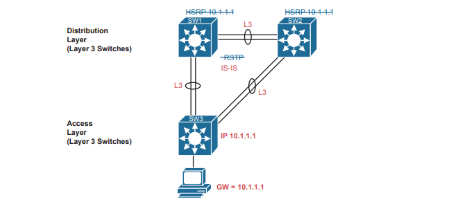
As far as the topology, traditional campus design does tell us how to connect devices, but SDA does not have to follow those traditional rules. With a greenfield SDA deployment—that is, all new gear that you can allow to be configured by DNA Center—DNA Center will configure the devices’ underlay configuration to use a routed access layer. Because DNA Center knows it can configure the switches without concern of harming a production network, it chooses the best underlay configuration to support SDA. That best configuration happens to use a design called a routed access layer design, which has these features:
- All switches act as Layer 3 switches.
- The switches use the IS-IS routing protocol.
- All links between switches (single links, EtherChannels) are routed Layer 3 links (not Layer 2 links).
- As a result, STP/RSTP is not needed, with the routing protocol instead choosing which links to use based on the IP routing tables.
- The equivalent of a traditional access layer switch—an SDA edge node—acts as the default gateway for the endpoint devices, rather than distribution switches.
- As a result, HSRP (or any FHRP) is no longer needed.
The SDA Overlay
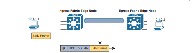
When you first think of the SDA overlay , think of this kind of sequence. First, an endpoint sends a frame that will be delivered across the SDA network. The first SDA node to receive the frame encapsulates the frame in a new message—using a tunneling specification called VXLAN—and forwards the frame into the fabric. Once the ingress node has encapsulated the original frame in VXLAN, the other SDA nodes forward the frame based on the VXLAN tunnel details. The last SDA node removes the VXLAN details, leaving the original frame, and forwards the original frame on toward the destination endpoint.
VXLAN Tunnels in the Overlay (Data Plane)
SDA has many additional needs beyond the simple message delivery—needs that let it provide improved functions. To that end, SDA does not only route IP packets or switch Ethernet frames. Instead, it encapsulates incoming data link frames in a tunneling technology for delivery across the SDA network, with these goals in mind:
- The VXLAN tunneling (the encapsulation and de-encapsulation) must be performed by the ASIC on each switch so that there is no performance penalty. (That is one reason for the SDA hardware compatibility list: the switches must have ASICs that can perform the work.)
- The VXLAN encapsulation must supply header fields that SDA needs for its features, so the tunneling protocol should be flexible and extensible, while still being supported by the switch ASICs.
- The tunneling encapsulation needs to encapsulate the entire data link frame instead of encapsulating the IP packet. That allows SDA to support Layer 2 forwarding features as well as Layer 3 forwarding features.
To achieve those goals, when creating SDA, Cisco chose the Virtual Extensible LAN (VXLAN) protocol to create the tunnels used by SDA. When an SDA endpoint (for example, an end-user computer) sends a data link frame into an SDA edge node, the ingress edge node encapsulates the frame and sends it across a VXLAN tunnel to the egress edge node.To support the VXLAN encapsulation, the underlay uses a separate IP address space as compared with the rest of the enterprise, including the endpoint devices that send data over the SDA network. The overlay tunnels use addresses from the enterprise address space. For instance, imagine an enterprise used these address spaces:
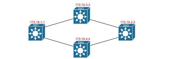
- 10.0.0.0/8: Entire enterprise
- 172.16.0.0/16: SDA underlay
To make that work, first the underlay would be built using the 172.16.0.0/16 IPv4 address space, with all links using addresses from that address space. As an example, Figure shows a small SDA design, with four switches, each with one underlay IP address shown (from the 172.16.0.0/16 address space).
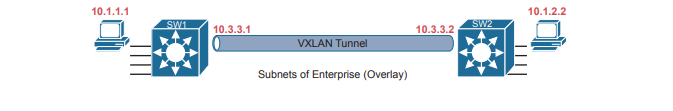
The overlay tunnel creates a path between two fabric edge nodes in the overlay IP address space—that is, in the same address space used by all the endpoints in the enterprise. Figure emphasizes that point by showing the endpoints (PCs) on the left and right, with IP addresses in network 10.0.0.0/8, with the VXLAN overlay tunnel shown with addresses also from 10.0.0.0/8.
LISP for Overlay Discovery and Location (Control Plane)
Ignore SDA for a moment, and think about traditional Layer 2 switching and Layer 3 routing. How do their control planes work? In other words, how do these devices discover the possible destinations in the network, store those destinations, so that the data plane has all the data it needs when making a forwarding decision? To summarize:
- Traditional Layer 2 switches learn possible destinations by examining the source MAC addresses of incoming frames, storing those MAC addresses as possible future destinations in the switch’s MAC address table. When new frames arrive, the Layer 2 switch data plane then attempts to match the Ethernet frame’s destination MAC address to an entry in its MAC address table.
- Traditional Layer 3 routers learn destination IP subnets using routing protocols, storing routes to reach each subnet in their routing tables. When new packets arrive, the Layer 3 data plane attempts to match the IP packet’s destination IP address to some entry in the IP routing table.
Nodes in the SDA network do not do these same control plane actions to support endpoint traffic. Just to provide a glimpse into the process , consider this sequence, which describes one scenario:
- Fabric edge nodes—SDA nodes that connect to the edge of the SDA fabric—learn the location of possible endpoints using traditional means, based on their MAC address, individual IP address, and by subnet, identifying each endpoint with an endpoint identifier (EID).
- The fabric edge nodes register the fact that the node can reach a given endpoint (EID) into a database called the LISP map server.
- The LISP map server keeps the list of endpoint identifiers (EIDs) and matching routing locators (RLOCs) (which identify the fabric edge node that can reach the EID).
- In the future, when the fabric data plane needs to forward a message, it will look for and find the destination in the LISP map server’s database.