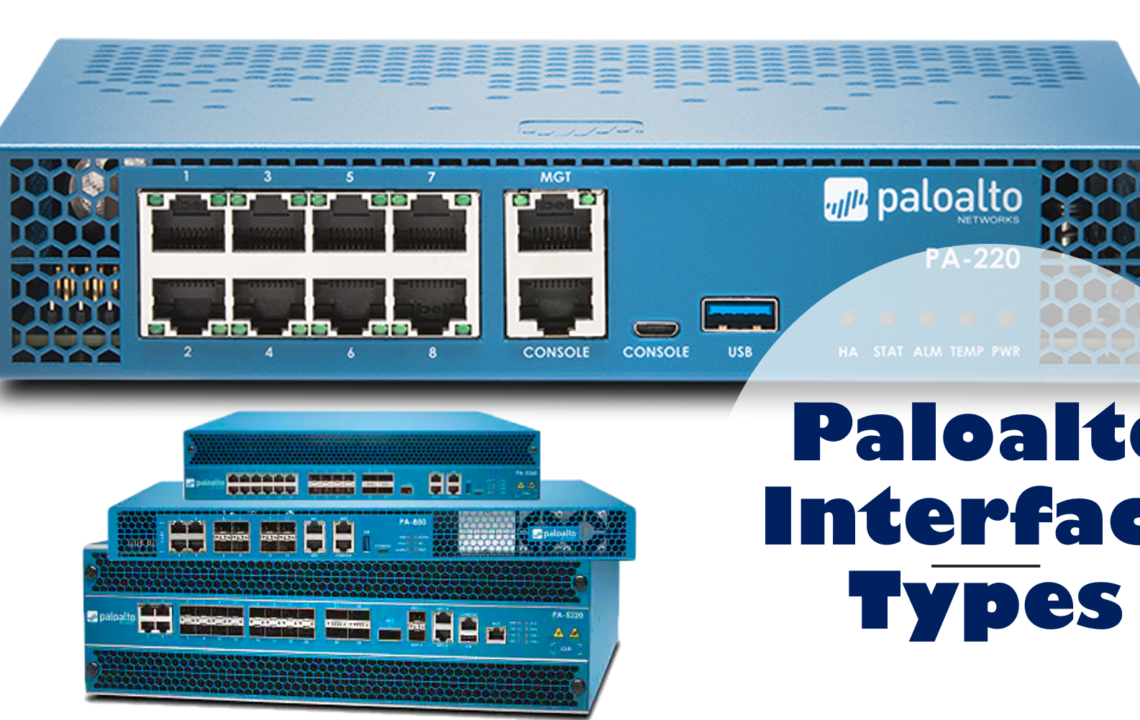
A single firewall can freely intermix interface types to meet any integration need. The decision about which interface configuration to choose depends on functional need and existing network integration requirements. Paloalto firewall supports several types of Ethernet (Physical) interfaces:
- Tap Mode
- Virtual Wire Mode
- Layer 2 Mode
- Layer 3 Mode
- HA
Tap Mode
A network tap is a device that provides a way to access data that is flowing across a computer
network. TAP mode deployment allows you to passively monitor traffic flows across a network using
a switch SPAN or mirror port.
A switch SPAN or mirror port permits the copying of traffic from ports on the switch to the tap interface of the firewall, providing a one-way flow of copied network traffic into the firewall. This configuration allows the firewall to perform detection of traffic and threats but prevents any enforcement action because the traffic does not flow through the firewall back to the environment.
By deploying the firewall in TAP mode, you can get visibility into which applications are running on the
network without having to make any changes to your network design. When the firewall is in TAP mode, it
also can identify threats on your network. Remember, however, that the traffic is not running through the
firewall when the firewall is in TAP mode, so no action can be taken on the traffic, including blocking traffic that includes threats or applying QoS traffic control.
Virtual Wire Mode (vWire)
In a virtual wire deployment, you install a firewall transparently on a network segment by binding two
firewall ports (interfaces) together. The virtual wire logically connects the two interfaces; hence, the virtual
wire is internal to the firewall.
Use a virtual wire deployment only when you want to seamlessly integrate a firewall into a topology, and the two connected interfaces on the firewall do not need to perform any switching or routing. For these two interfaces, the firewall is considered a bump in the wire. A virtual wire deployment simplifies firewall installation and configuration because you can insert the firewall into an existing topology without assigning MAC or IP addresses to the interfaces, redesigning the network, or reconfiguring surrounding network devices. The virtual wire supports blocking or allowing traffic based on virtual LAN (VLAN) tags. It also supports Security policy rules, App-ID, Content-ID, User-ID, decryption, LLDP, active/passive and active/active HA, QoS, zone protection (with some exceptions), non-IP protocol protection, DoS protection, packet buffer protection, tunnel content inspection, and NAT.
Layer 2 Interface Mode
In a Layer 2 deployment, the firewall provides switching between two or more networks. Devices are
connected to a Layer 2 segment; the firewall forwards the frames to the proper port, which is associated
with the MAC address that is identified in the frame. Configure a Layer 2 interface when switching is
required.
Layer 3 Mode
In a Layer 3 deployment, the firewall routes traffic between multiple ports using TCP/IP addressing. Before
you can configure Layer 3 interfaces, you must configure the virtual routers that you want the firewall to use to route the traffic for each Layer 3 interface.
Layer 3 deployments require more network planning and configuration preparation than do most other
firewall interfaces, but they remain the most widely used in firewall deployments. Palo Alto Networks
supports both IPv4 and IPv6 simultaneously through a dual stack implementation when IPv6 is required. Each Layer 3 interface must be configured with an IPv4 and/or an IPv6 address, zone name assignment, and the attached virtual router that services the traffic on the interface.
HA
High Availability (HA) interfaced are used in HA cluster as name states. Each HA interface has a specific function: one interface is for configuration synchronization and heartbeats, and the other interface is for state synchronization. If active/active high availability is enabled, the firewall can use a third HA interface to forward packets.
Apart from physical interface in Paloalto firewall, it also supports logical interfaces. Let’s explore them:
- Aggerate Interface
- Tunnel Interface
- Loopback Interface
- Decrypt Mirror
Aggregate
An Aggregate Ethernet (AE) interface group uses IEEE 802.1AX link aggregation to combine multiple Ethernet interfaces into a single virtual interface that connects the firewall to another network device or another firewall. An AE interface group increases the bandwidth between peers by load balancing traffic across the combined interfaces. It also provides redundancy: When one interface fails, the remaining interfaces continue to support traffic.
Before you configure an AE interface group, you must configure its interfaces. Hardware media can differ
among the interfaces assigned to an aggregate group. For example, you can mix fiber optic and copper. But the bandwidth and interface type must be the same. You can add at least 8 AE interface groups per firewall, although some firewall models support 16, and each group can have up to 8 interfaces. Aggregate interface creation begins with the definition of an Aggregate Interface group, after which
individual interfaces are added to the group.
Tunnel Interface
In a VPN tunnel setup, the Layer 3 interface at each end must have a logical tunnel interface for the firewall to connect to and establish a VPN tunnel. A tunnel interface is a logical (virtual) interface that is used to deliver traffic between two endpoints. If you configure a proxy ID, the proxy ID is counted toward any IPSec tunnel capacity. The tunnel interface must belong to a security zone to apply policy, and it must be assigned to a virtual router to use the existing routing infrastructure. Ensure that the tunnel interface and the physical interface are assigned to the same virtual router so that the firewall can perform a route lookup and determine the appropriate tunnel to use.
The Layer 3 interface that the tunnel interface is attached to typically belongs to an external zone, for
example, the untrust zone. Although the tunnel interface can be in the same security zone as the physical
interface, you can create a separate zone for the tunnel interface for added security and better visibility. If
you create a separate zone for the tunnel interface, such as a VPN zone, you will need to create Security
policies to allow traffic to flow between the VPN zone and the trust zone.
A tunnel interface does not require an IP address to route traffic between the sites. An IP address is required only if you want to enable tunnel monitoring or if you are using a dynamic routing protocol to route traffic across the tunnel. With dynamic routing, the tunnel IP address serves as the next hop IP address for routing traffic to the VPN tunnel.
Loopback Interface
Loopback interfaces are Layer 3 interfaces that exist only virtually and connect to virtual routers in
the firewall. Loopback interfaces are used for multiple network engineering and implementation purposes. They can be destination configurations for DNS sinkholes, Global Protect service interfaces (e.g., portals and gateways), routing identification, and more.
Decrypt Mirror
Decrypt mirror is a special configuration that supports the routing of decrypted traffic copies through an
external interface to a data loss prevention (DLP) service. DLP is a product category for products that scan
internet-bound traffic for keywords and patterns that identify sensitive information.


