Layer 2 switch provides connectivity between two or more different devices within a local area network. Switch allow data transfer between end devices in a network. When the data packet is for out of LAN, the packet sent to the gateway router. A Switch is a networking device which works at Data link layer in networking. A Switch receive and transmit the data packets between different end devices. We required to configure and verify Interswitch connectivity for data transfer between different devices. Switch inspect the header section of the received packet to check the destination IP address and MAC address then forward the packet accordingly. A switch can connect the computers via Ethernet port, Fast Ethernet port and optic fiber port. Switch works on its operating software which store the MAC address of devices connected with the various interfaces of switch.
Trunk Ports
Configuring VLANs on a single switch requires only a little effort: you simply configure each port to tell it the VLAN number to which the port belongs. With multiple switches, you have to consider additional concepts about how to forward traffic between the switches. When you are using VLANs in networks that have multiple interconnected switches, the switches need to use VLAN trunking on the links between the switches. VLAN trunking causes the switches to use a process called VLAN tagging, by which the sending switch adds another header to the frame before sending it over the trunk. This extra trunking header includes a VLAN identifier (VLAN ID) field so that the sending switch can associate the frame with a particular VLAN ID, and the receiving switch can then know in what VLAN each frame belongs.
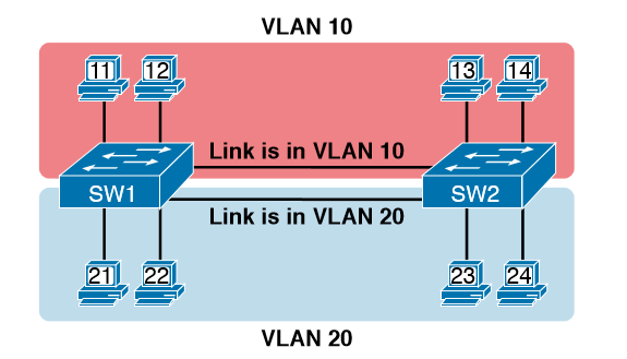
Here in example that demonstrates VLANs that exist on multiple switches, but it does not use trunking. First, the design uses two VLANs: VLAN 10 and VLAN 20. Each switch has two ports assigned to each VLAN, so each VLAN exists in both switches. To forward traffic in VLAN 10 between the two switches, the design includes a link between switches, with that link fully inside VLAN 10. Likewise, to support VLAN 20 traffic between switches, the design uses a second link between switches, with that link inside VLAN 20.
VLAN Tagging Concepts
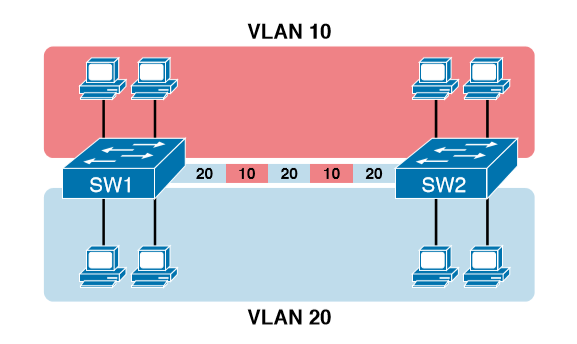
VLAN trunking creates one link between switches that supports as many VLANs as you need. As a VLAN trunk, the switches treat the link as if it were a part of all the VLANs. At the same time, the trunk keeps the VLAN traffic separate, so frames in VLAN 10 would not go to devices in VLAN 20, and vice versa, because each frame is identified by VLAN number as it crosses the trunk. Figure 8-4 shows the idea, with a single physical link between the two switches.
The use of trunking allows switches to forward frames from multiple VLANs over a single physical connection by adding a small header to the Ethernet frame. For example, Figure shows PC11 sending a broadcast frame on interface Fa0/1 at Step 1. To flood the frame, switch SW1 needs to forward the broadcast frame to switch SW2. However, SW1 needs to let SW2 know that the frame is part of VLAN 10, so that after the frame is received, SW2 will flood the frame only into VLAN 10, and not into VLAN 20. So, as shown at Step 2, before sending the frame, SW1 adds a VLAN header to the original Ethernet frame, with the VLAN header listing a VLAN ID of 10 in this case.
802.1Q and ISL VLAN Trunking Protocol
Cisco has supported two different trunking protocols over the years: Inter-Switch Link (ISL) and IEEE 802.1Q. Cisco created the ISL years before 802.1Q, in part because the IEEE had not yet defined a VLAN trunking standard. Today, 802.1Q has become the more popular trunking protocol, with Cisco not even bothering to support ISL in many of its switch models today.
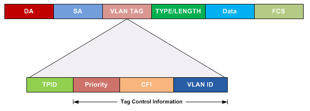
While both ISL and 802.1Q tag each frame with the VLAN ID, the details differ. 802.1Q inserts an extra 4-byte 802.1Q VLAN header into the original frame’s Ethernet header, as shown at the top of Figure 8-6. As for the fields in the 802.1Q header, only the 12-bit VLAN ID field inside the 802.1Q header matters for topics discussed in this book. This 12-bit field supports a theoretical maximum of 212 (4096) VLANs, but in practice it supports a maximum of 4094. (Both 802.1Q and ISL use 12 bits to tag the VLAN ID, with two reserved values [0 and 4095].)
Cisco switches break the range of VLAN IDs (1–4094) into two ranges: the normal range and the extended range. All switches can use normal-range VLANs with values from 1 to 1005. Only some switches can use extended-range VLANs with VLAN IDs from 1006 to 4094. The rules for which switches can use extended-range VLANs depend on the configuration of the VLAN Trunking Protocol (VTP).
802.1Q
802.1Q also defines one special VLAN ID on each trunk as the native VLAN (defaulting to use VLAN 1). By definition, 802.1Q simply does not add an 802.1Q header to frames in the native VLAN. When the switch on the other side of the trunk receives a frame that does not have an 802.1Q header, the receiving switch knows that the frame is part of the native VLAN. Note that because of this behavior, both switches must agree on which VLAN is the native VLAN.
Native
The 802.1Q native VLAN provides some interesting functions, mainly to support connections to devices that do not understand trunking. For example, a Cisco switch could be cabled to a switch that does not understand 802.1Q trunking. The Cisco switch could send frames in the native VLAN—meaning that the frame has no trunking header—so that the other switch would understand the frame. The native VLAN concept gives switches the capability of at least passing traffic in one VLAN (the native VLAN), which can allow some basic functions, like reachability to telnet into a switch.
Forwarding Data Between VLANs (Inter VLAN Routing)
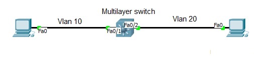
When including VLANs in a campus LAN design, the devices in a VLAN need to be in the same subnet. Following the same design logic, devices in different VLANs need to be in different subnets. To forward packets between VLANs, the network must use a device that acts as a router. You can use an actual router, as well as some other switches that can perform some functions like a router. These switches that also perform Layer 3 routing functions go by the name multilayer switch or Layer 3 switch.
A Switched Virtual Interface (SVI) is a virtual LAN (VLAN) of switch ports represented by one interface to a routing or bridging system. There is no physical interface for the VLAN and the SVI provides the Layer 3 processing for packets from all switch ports associated with the VLAN. Switch has supervisor engine which has a pool of MAC address and a MAC is given to Logical interface from the same pool.
Switch#int fa0/1
Switch#switchport mode access
Switch#switchport access vlan 10
^z
Switch#int fa0/2
Switch#switchport mode access
Switch#switchport access vlan 20
Once you inserted interface into Vlans you have to create SVi for both vlan and run routing command to perform routing.Switch# int vlan10
Switch# ip add 10.0.0.10 255.0.0.0
^z
Switch#int vlan20
Switch#ip add 20.0.0.10 255.0.0.0
Switch#ip routing [Run routing command]
Note: Give IP address to Pc and Default gateway according to your SVIs IP and check the communication.
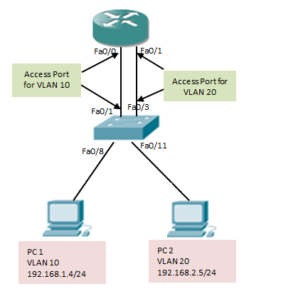
The only way to get off a layer two network segment is through a layer three device; commonly referred to as a Default Gateway for host machines. A single Router can utilize an 802.1q trunk link to place a sub-interface in each VLAN using a single physical link and technically have interfaces in all VLAN’s. A Sub-Interface is a logical interface partitioned off from a physical interface. A sub-interface allows you to have multiple interface configurations on a single physical interface. In this lab you’ll use sub-interfaces to match the VLAN’s in the trunk to allow for interfaces in each VLAN and accomplish inter-vlan routing for the hosts as the router has an interface in each layer three network.
Configuration:
To create a new sub-interface you’ll use the interface fa0/0.# command in global configuration mode. To enable the sub-interface to use 802.1q you’ll use the encapsulation dot1q # command whereas # is the dot1q VLAN tag.
R1>enable
R1#configure terminal
Enter configuration commands, one per line. End with CNTL/Z.
R1(config)#interface fa0/0
R1(config-if)#no shut
R1(config-if)#interface fa0/0.20
R1(config-subif)#encapsulation dot1q 20
R1(config-subif)#ip add 10.1.20.1 255.255.255.0
R1(config-subif)#exit
R1(config)#
Note: The above command is to create sub interface for single Vlan 20 with encapsulation dot1q. You have to configure another subinterface inorder to communicate VLANs. If you have commected PCs directly then try ping after creating Sub interface with Default gateway as sub interface ip. If you are using Router as PC then follow below command:
R2>enable
R2#configure terminal
Enter configuration commands, one per line. End with CNTL/Z.
R2(config)#no ip routing
R2(config)#ip default-gateway 10.1.20.1
R2(config)#end