Fiber optics have been inspected and cleaned to ensure the proper passage of light. While this process is not new, it is growing in importance as our our dependence on the capacity and other benefits of fiber optics surges.
Here we will be knowing about important tools required to work with Fiber Optics to keep data flow precious without disturbance.
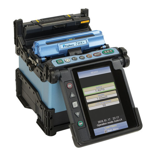
Fiber Splicer
Fiber Splicer is Optical fusion machine for joining 2 Fiber. Fusion Splicing is a preferred way to join two fibers together by using heat. Whether the fiber was broken or not long enough, a fusion splicer will make your job easier. Splicing fiber optic cable is fairly simple procedure. Prepared fiber ends are placed in the splicer and automatically aligned and then fused together. This method ensures greater reliability with less light being scattered or reflected back by the splice. The splice itself if done correctly should be as strong as the original optical fiber.
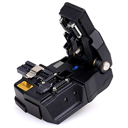
Fiber Cleaver
Developed by Lucent Technologies, the LC fiber optic connector has become the ubiquitous fiber connector for today’s optical telecom applications, especially for connections with SFP and SFP+ fiber transceivers. As one popular SFF (small form factor) connector, LC fiber connector has a ferrule of 1.25mm, which make it perfect for high density cabling. There are single mode LC connector and multimode LC connector. And based on the connector construction, LC connector also can be divided into LC duplex and simplex connector.
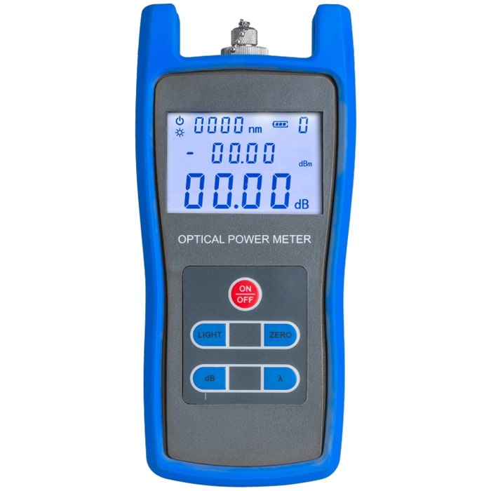
Optical Power Meter
An optical power meter (OPM) is a device used measure the power in an optical signal. The term usually refers to a device for testing average power in fiber optic systems. Other general purpose light power measuring devices are usually called radiometers, photometers, laser power meters (can be photodiode sensors or thermopile laser sensors), light meters or lux meters.
A typical optical power meter consists of a calibrated sensor, measuring amplifier and display. The sensor primarily consists of a photodiode selected for the appropriate range of wavelengths and power levels. On the display unit, the measured optical power and set wavelength is displayed. Power meters are calibrated using a traceable calibration standard.
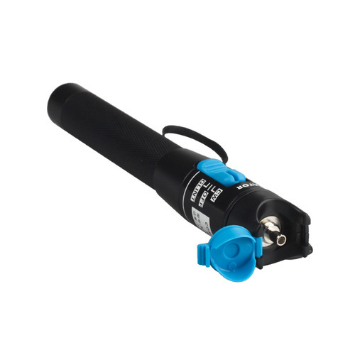
Visual Fault Locator (VFL)
This device is inexpensive way to quickly identify pinched fibers, a breakpoint, poor connections, bending or bad splices. A red laser injects visible light into a optical fiber. When the red light shows through at a break, it is easy for a tech to spot the problem. It is important to note that that a microbends do not allow as much light to escape through the fiber jacket therefore it may be necessary to darken the area to better see the damaged area.
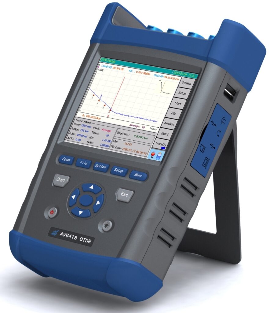
Optical Time-Domain Reflectometer (OTDR)
An OTDR is an optoelectronic instrument used to characterize an optical fiber. An OTDR is the optical equivalent of an electronic time domain reflectometer. It injects a series of optical pulses into the fiber under test and extracts, from the same end of the fiber, light that is scattered (Rayleigh backscatter) or reflected back from points along the fiber. The scattered or reflected light that is gathered back is used to characterize the optical fiber. This is equivalent to the way that an electronic time-domain meter measures reflections caused by changes in the impedance of the cable under test. The strength of the return pulses is measured and integrated as a function of time, and plotted as a function of fiber length.
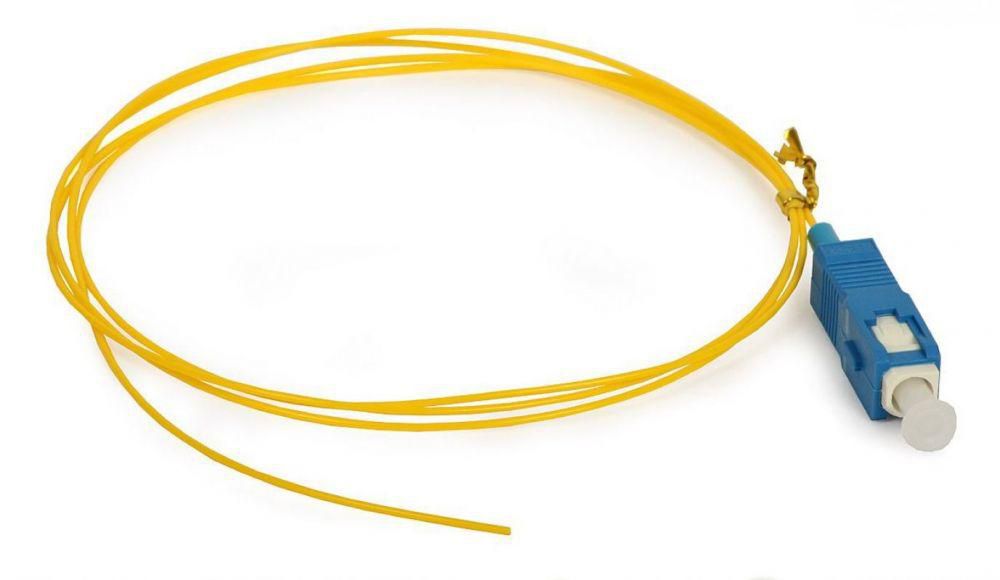
Pigtails
A fiber pigtail is a single, short, usually tight-buffered, optical fiber that has an optical connector pre-installed on one end and a length of exposed fiber at the other end.
The end of the pigtail is stripped and fusion spliced to a single fiber of a multi-fiber trunk. Splicing of pigtails to each fiber in the trunk “breaks out” the multi-fiber cable into its component fibers for connection to the end equipment.
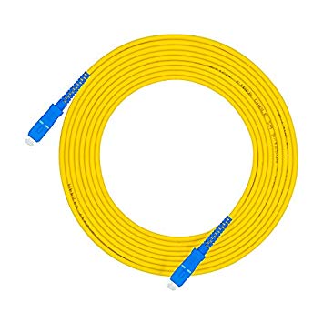
Fiber Patch Cord and Connectors
A fiber-optic patch cord is a fiber-optic cable capped at either end with connectors that allow it to be rapidly and conveniently connected to CATV, an optical switch or other telecommunication equipment. Its thick layer of protection is used to connect the optical transmitter, receiver, and the terminal box. This is known as “interconnect-style cabling”.
Connectors and splices link the ends of two fibers both optically and mechanically. The two are not interchangeable. A connector is mounted on the end of a cable or optical device so it can be attached to other cables or devices.
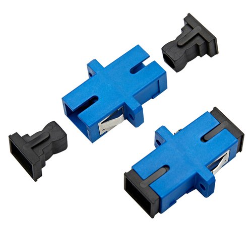
Fiber Optics Adaptors / Couplers
Fiber optic adapters (also called couplers) are designed to connect two fiber optic cables together. Fiber optic adapters are typically connecting cables with similar connectors (SC to SC, LC to LC, etc.). Some adapters, called “hybrid”, accept different types of connectors (ST to SC, LC to SC, etc.).
Fiber Optics Fast Connectors
The widespread use of fiber-to-the-home (FTTH) facilitates the rise of the fiber optic fast connector, it is small in size and fast terminating, and are less expensive and have high stability. At the end point of the Fiber sometime you may not be able to slice with pigtails, at that point connecting fast connectors are best way. Example, if the endpoint connection is at top of pole where you can not splice, at that moment you can apply Fast Connectors. Process to apply Fast Connectors is same like splicing but instead of splicing we connect fast connectors after cleaving.