Routers route IPv4 packets. That simple statement actually carries a lot of hidden meaning. For routers to route packets, routers follow a routing process. That routing process relies on information called IP routes. Each IP route lists a destination—an IP network, IP subnet, or some other group of IP addresses. Each route also lists instructions that tell the router where to forward packets sent to addresses in that IP network or subnet. For routers to do a good job of routing packets, routers need to have a detailed, accurate list of IP routes. Routers use three methods to add IPv4 routes to their IPv4 routing tables. Routers first learn connected routes, which are routes for subnets attached to a router interface. Routers can also use static routes, which are routes created through a configuration command (ip route) that tells the router what route to put in the IPv4 routing table. And routers can use a routing protocol, in which routers tell each other about all their known routes, so that all routers can learn and build routes to all networks and subnets.
IP routing—the process of forwarding IP packets—delivers packets across entire TCP/IP networks, from the device that originally builds the IP packet to the device that is supposed to receive the packet. In other words, IP routing delivers IP packets from the sending host to the destination host. The complete end-to-end routing process relies on network layer logic on hosts and on routers. The sending host uses Layer 3 concepts to create an IP packet, forwarding the IP packet to the host’s default gateway (default router). The process requires Layer 3 logic on the routers as well, by which the routers compare the destination address in the packet to their routing tables, to decide where to forward the IP packet next.
The routing process also relies on data-link and physical details at each link. IP routing relies on serial WAN links, Ethernet WAN links, Ethernet LANs, wireless LANs, and many other networks that implement data-link and physical layer standards. These lower-layer devices and protocols move the IP packets around the TCP/IP network by encapsulating and transmitting the packets inside data-link layer frames.
- Routing Protocol code
- Prefix
- Network Mask
- Next Hop
- Administrative Distance (AD)
- Metric
- Gateway of last resort
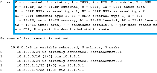
Routing protocol code
Routing protocol code identifies by which routing protocol each route was learned.
Common routing protocol codes include:
C – Connected
S – Static
I – IGRP
R – RIP
B – BGP
D – EIGRP
EX – EIGRP external
O – OSPF
And more…
Prefix
A prefix is simply the network address. In a routing table, the prefix is the destination network address. A prefix-length is just the shorthand way to express a subnet mask using CIDR notation. If the subnet mask is 255.255.255.0 than the prefix-length is /24.
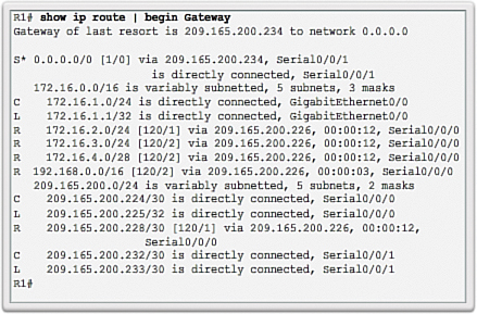
Reading the routing table from top to bottom you can see the prefixes and prefix-lengths for the destination networks:
0.0.0.0/0 The prefix is 0.0.0.0 and the prefix-length is /0
172.16.0.0/16 The prefix is 172.16.0.0 and the prefix-length is /16, but this isn’t a route just a summary
172.16.1.0/24 The prefix is 172.16.1.0 and the prefix-length is /24
172.16.1.1/32 You got this
172.16.2.0/24 I’ll show a couple more to make sure
172.16.3.0/24
172.16.4.0/28
192.168.0.0/16 The prefix is 192.168.0.0 and the prefix-length is /16
209.165.200.0/24
209.165.200.224/30
209.165.200.224/32
209.165.200.225/32 The prefix is 209.165.200.225 and the prefix-length is /32
209.165.200.228/30
209.165.200.232/30
209.165.200.233/32
Next Hop
Connected networks and Local networks do not have a next hop, The first next hop address in the routing table is for the RIP route to network 172.16.2.0/24. The next hop is 209.165.200.226, The next hop to get to the network 172.16.3.0/24 is 209.165.200.226, Looking at the RIP route to the 209.165.200.228/30 network, it’s next hop is 209.165.200.226.
Administrative Distance (AD)
Administrative distance is what is used to select the best path when a router has two different paths to the same destination via two different routing protocols. Most routing protocols are not compatible with other protocols. In a network with multiple routing protocols, being able to select the best path between multiple protocols is critical. Administrative distance defines the reliability of a routing protocol. Each routing protocol is prioritized in order of most to least reliable (believable) with the help of an administrative distance value. IPv6 uses the same distances as IPv4.
Admin distance is the first criterion that a router uses to determine which routing protocol to use if two protocols provide route information for the same destination. Admin distance is a measure of the trustworthiness of the source of the routing information. Admin distance has only local significance, and is not advertised in routing updates. The smaller the admin distance value, the more reliable the protocol. For example, if a router receives a route to a certain network from both Open Shortest Path First (OSPF) (default administrative distance – 110) and Interior Gateway Routing Protocol (IGRP) (default administrative distance – 100), the router chooses IGRP because IGRP is more reliable. This means the router adds the IGRP version of the route to the routing table. Default Administrative Distances:
| Routing Protocol | Administrative Distance |
|---|---|
| Connected | 0 |
| Static | 1 |
| BGP (external) | 20 |
| EIGRP | 90 |
| IGRP | 100 |
| OSPF | 110 |
| ISIS | 115 |
| RIP | 120 |
| BGP (internal) | 200 |
Metric
The metric is a value produced by the routing protocol’s algorithm. The metric value determines the best path to a destination network within a routing protocol. To determine the metric: RIP uses hop count, EIGRP uses K values, OSPF uses reference bandwidth. Metric is used to compare routes to a destination by the same routing protocol Lower values indicate preferred routes.
EIGRP Metric Calculation
Enhanced Interior Gateway Routing Protocol (EIGRP) uses a complex equation to find the Route Metric value. EIGRP consider the following network performance related attributes to calculate the EIGRP metric value.
1) Bandwidth
2) Delay
3) Reliability and
4) Load
EIGRP Metric = 256*((K1*Bandwidth) + (K2*Bandwidth)/(256-Load) + K3*Delay)*(K5/(Reliability + K4)))
By default, the values of K1 and K3 are set to 1, and K2, K4 and K5 are set to 0. Hence the above equation is deduced to
EIGRP Metric = 256*(Bandwidth + Delay)
Where,
• Bandwidth = 10000000/bandwidth(i), where bandwidth(i) is the least bandwidth of all outgoing interfaces on the route to the destination network represented in kilobits.
• Delay = delay(i) where delay(i) is the sum of the delays configured on the interfaces, on the route to the destination network, in tens of microseconds.
OSPF Metric Calculation
Open Shortest Path First (OSPF) uses “Cost” as the value of metric and uses a Reference Bandwidth of 100 Mbps for cost calculation. The formula to calculate the cost is Reference Bandwidth divided by interface bandwidth. For example, in the case of 10 Mbps Ethernet, OSPF Metric Cost value is 100 Mbps / 10 Mbps = 10. The default Reference Bandwidth of OSPF is 100 Mbps and the default OSPF cost formula doesn’t differentiate between interfaces with bandwidth faster than 100 Mbps. These days, 1 Gbps and 10 Gbps links are also common.
If you want to change the default behavior, the cost formula can be adjusted using the “auto-cost” command under the OSPF routing process. If you are changing the default OSPF Reference Bandwidth, make sure that you have changed the OSPF Reference Bandwidth in all your OSPF Routers.
Following table lists OSPF default Cost values for different interface bandwidths.
| Bandwidth | OSPF Cost |
|---|---|
| 100 Gbps | 1 |
| 40 Gbps | 1 |
| 10 Gbps | 1 |
| 1 Gbps | 1 |
| 100 Mbps | 1 |
| 10 Mbps | 10 |
| 1.54 Mbps | 64 |
| 768 Kbps | 133 |
| 384 Kbps | 266 |
| 128 Kbps | 781 |
Gateway of last resot
A Gateway of Last Resort or Default gateway is a route used by the router when no other known route exists to transmit the IP packet. Known routes are present in the routing table. Hence, any route not known by the routing table is forwarded to the default route. Each router which receives this packet will treat the packet the same way, if the route is known, packet will be forwarded to the known route.
You can use any of the following commands to configure the gateway of last resort:
#ip default-gateway a.b.c.d
#ip default-network a.b.c.d
#ip route 0.0.0.0 0.0.0.0 a.b.c.d
Note: If you configure multiple networks as candidate default routes using the ip default-network command, the network that has the lowest administrative distance is chosen as the network for the gateway of last resort. If all the networks have the same administrative distance then the network listed first in the routing table (show ip route lists the routing table) is chosen as the network for the gateway of last resort. If you use both the ip default-network and ip route 0.0.0.0 0.0.0.0 commands to configure candidate default networks, and the network used by the ip default-network command is known statically, the network defined with the ip default-network command takes precedence and is chosen for the gateway of last resort. Otherwise if the network used by the ip default-network command is derived by a routing protocol, the ip route 0.0.0.0 0.0.0.0 command, which has a lower administrative distance, takes precedence and is chosen for the gateway of last resort. If you use multiple ip route 0.0.0.0 0.0.0.0 commands to configure a default route, traffic is load-balanced over the multiple routes.
Use the ip default-gateway command when ip routing is disabled on a Cisco router. Use the ip default-network and ip route 0.0.0.0 0.0.0.0 commands to set the gateway of last resort on Cisco routers that have ip routing enabled. The way in which routing protocols propagate the default route information varies for each protocol


