The Cisco UWN solution can control up to 512 WLANs for lightweight access points. Each WLAN has a separate WLAN ID (1 through 512), a separate profile name, and a WLAN SSID. All controllers publish up to 16 WLANs to each connected access point, but you can create up to 512 WLANs and then selectively publish these WLANs (using access point groups) to different access points to better manage your wireless network. You can configure WLANs with different Service Set Identifiers (SSIDs) or with the same SSID. An SSID identifies the specific wireless network that you want the controller to access.
Configuring a WLAN
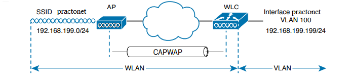
A wireless LAN controller and an access point work in concert to provide network connectivity to wireless clients. From a wireless perspective, the AP advertises a Service Set Identifier (SSID) for the client to join. From a wired perspective, the controller connects to a virtual LAN (VLAN) through one of its dynamic interfaces. To complete the path between the SSID and the VLAN, as illustrated in Figure, you must first define a WLAN on the controller.
The controller will bind the WLAN to one of its interfaces and then push the WLAN configuration out to all of its APs by default. From that point on, wireless clients will be able to learn about the new WLAN by receiving its beacons and will be able to probe and join the new BSS. Like VLANs, you can use WLANs to segregate wireless users and their traffic into logical networks. Users associated with one WLAN cannot cross over into another one unless their traffic is bridged or routed from one VLAN to another through the wired network infrastructure.
Before you begin to create new WLANs, it is usually wise to plan your wireless network first. In a large enterprise, you might have to support a wide variety of wireless devices, user communities, security policies, and so on. You might be tempted to create a new WLAN for every occasion, just to keep groups of users isolated from each other or to support different types of devices. Although that is an appealing strategy, you should be aware of two limitations:
- Cisco controllers support a maximum of 512 WLANs, but only 16 of them can be actively configured on an AP.
- Advertising each WLAN to potential wireless clients uses up valuable airtime.
Every AP must broadcast beacon management frames at regular intervals to advertise the existence of a BSS. Because each WLAN is bound to a BSS, each WLAN must be advertised with its own beacons. Beacons are normally sent 10 times per second, or once every 100 ms, at the lowest mandatory data rate. The more WLANs you have created, the more beacons you will need to announce them. Even further, the lower the mandatory data rate, the more time each beacon will take to be transmitted. The end result is this: if you create too many WLANs, a channel can be starved of any usable airtime. Clients will have a hard time transmitting their own data because the channel is overly busy with beacon transmissions coming from the AP. As a rule of thumb, always limit the number of WLANs to five or fewer; a maximum of three WLANs is best.
By default, a controller has a limited initial configuration, so no WLANs are defined. Before you create a new WLAN, think about the following parameters it will need to have:
- SSID string
- Controller interface and VLAN number
- Type of wireless security needed
As you work through this section, you will create the appropriate dynamic controller interface to support the new WLAN; then you will enter the necessary WLAN parameters. Each configuration step is performed using a web browser session that is connected to the WLC’s management IP address.
Step 1. Configure a RADIUS Server
If your new WLAN will use a security scheme that requires a RADIUS server, such as WPA2-Enterprise or WPA3-Enterprise, you will need to define the server first. Select Security > AAA > RADIUS > Authentication to see a list of servers that have already been configured, as shown in Figure. If multiple servers are defined, the controller will try them in sequential order. Click New to create a new server.
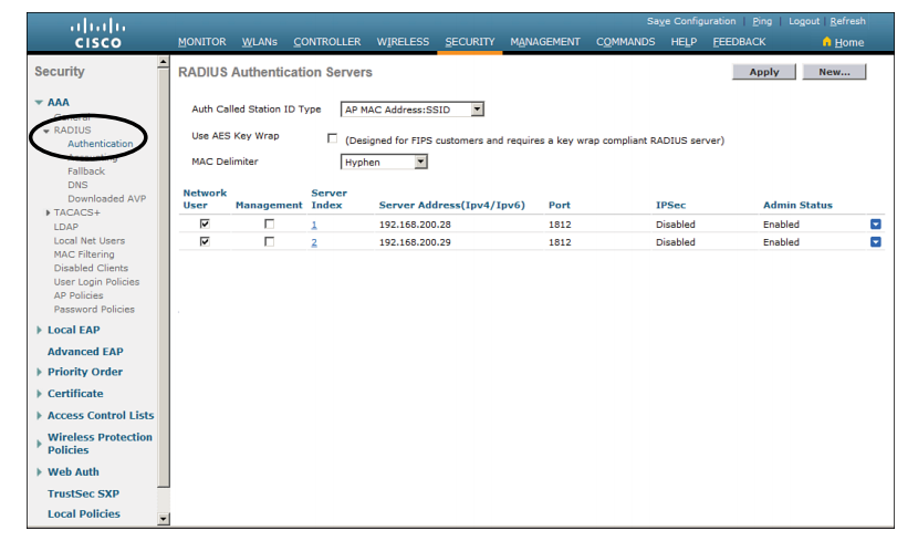
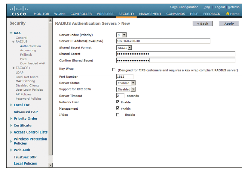
Next, enter the server’s IP address, shared secret key, and port number, as shown in Figure. Because the controller already had two other RADIUS servers configured, the server at 192.168.200.30 will be index number 3. Be sure to set the server status to Enabled so that the controller can begin using it. At the bottom of the page, you can select the type of user that will be authenticated with the server. Check Network User to authenticate wireless clients or Management to authenticate wireless administrators that will access the controller’s management functions. Click Apply to complete the server configuration.
Step 2. Create a Dynamic Interface
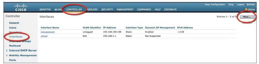
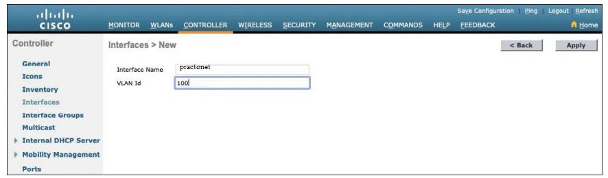
A dynamic interface is used to connect the controller to a VLAN on the wired network. When you create a WLAN, you will bind the dynamic interface (and VLAN) to a wireless network. To create a new dynamic interface, navigate to Controller > Interfaces. You should see a list of all the controller interfaces that are currently configured. In Figure, two interfaces named “management” and “virtual” already exist. Click the New button to define a new interface. Enter a name for the interface and the VLAN number it will be bound to. In second figure, the interface named practonet is mapped to wired VLAN 100. Click the Apply button.
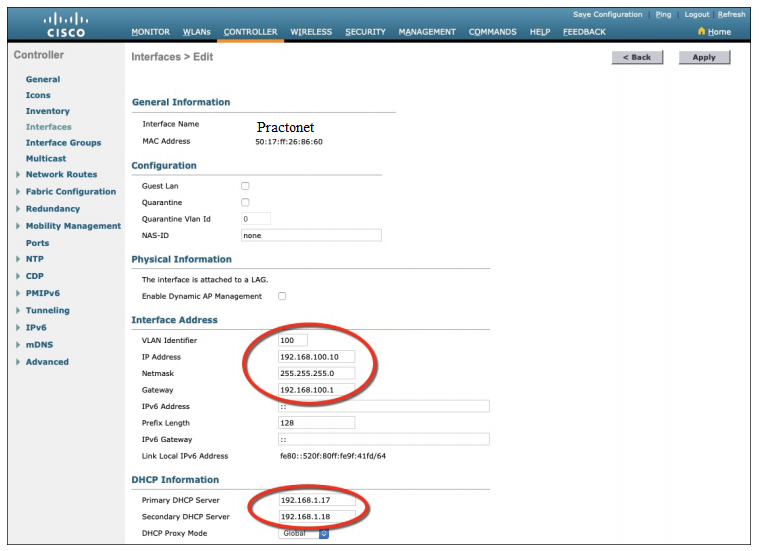
Next, enter the IP address, subnet mask, and gateway address for the interface. You should also define primary and secondary DHCP server addresses that the controller will use when it relays DHCP requests from clients that are bound to the interface. Figure below shows how the interface named Engineering has been configured with IP address 192.168.100.10, subnet mask 255.255.255.0, gateway 192.168.100.1, and DHCP servers 192.168.1.17 and 192.168.1.18. Click the Apply button to complete the interface configuration and return to the list of interfaces.
Step 3. Create a New WLAN
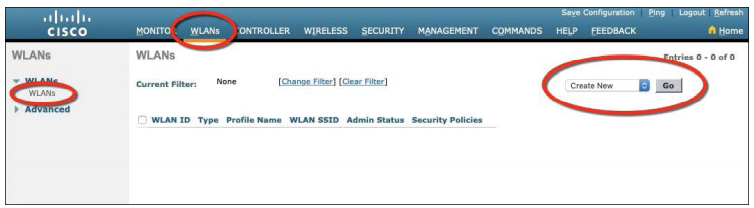
You can display a list of the currently defined WLANs by selecting WLANs from the top menu bar. The controller does not have any WLANs already defined. You can create a new WLAN by selecting Create New from the drop-down menu and then clicking the Go button.
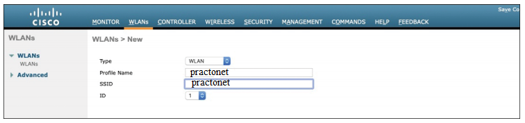
Next, enter a descriptive name as the profile name and the SSID text string. The profile name and SSID are identical, just to keep things straightforward. The ID number is used as an index into the list of WLANs that are defined on the controller. The ID number becomes useful when you use templates in Prime Infrastructure (PI) to configure WLANs on multiple controllers at the same time.
NOTE WLAN templates are applied to specific WLAN ID numbers on controllers. The WLAN ID is only locally significant and is not passed between controllers. As a rule, you should keep the sequence of WLAN names and IDs consistent across multiple controllers so that any configuration templates you use in the future will be applied to the same WLANs on each controller.
Click the Apply button to create the new WLAN. The next page will allow you to edit four categories of parameters, corresponding to the tabs across the top as shown. By default, the General tab is selected.
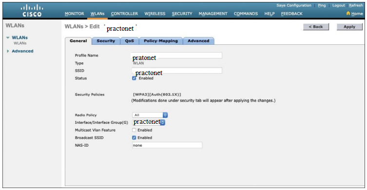
You can control whether the WLAN is enabled or disabled with the Status check box. Even though the General page shows a specific security policy for the WLAN (the default WPA2 with 802.1x), you can make changes in a later step through the Security tab. Under Radio Policy, select the type of radio that will offer the WLAN. By default, the WLAN will be offered on all radios that are joined with the controller. You can select a more specific policy with 802.11a only, 802.11a/g only, 802.11g only, or 802.11b/g only. For example, if you are creating a new WLAN for devices that have only a 2.4-GHz radio, it probably does not make sense to advertise the WLAN on both 2.4- and 5-GHz AP radios.
Next, select which of the controller’s dynamic interfaces will be bound to the WLAN. By default, the management interface is selected. The drop-down list contains all the interface names that are available. Finally, use the Broadcast SSID check box to select whether the APs should broadcast the SSID name in the beacons they transmit. Broadcasting SSIDs is usually more convenient for users because their devices can learn and display the SSID names automatically. In fact, most devices actually need the SSID in the beacons to understand that the AP is still available for that SSID. Hiding the SSID name, by not broadcasting it, does not really provide any worthwhile security. Instead, it just prevents user devices from discovering an SSID and trying to use it as a default network.
Configuring WLAN Security
Select the Security tab to configure the security settings. By default, the Layer 2 Security tab is selected. From the Layer 2 Security drop-down menu, select the appropriate security scheme to use. Table lists the types that are available.
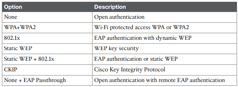
As you select a security type, be sure to remember which choices are types that have been deprecated or proven to be weak, and avoid them if possible. Further down the screen, you can select which specific WPA, WPA2, and WPA3 methods to support on the WLAN. You can select more than one, if you need to support different types of wireless clients that require several security methods. In below figure, WPA+WPA2 has been selected from the pull-down menu; then only WPA2 and AES encryption have been selected. WPA and TKIP have been avoided because they are legacy, deprecated methods. Under the Authentication Key Management section, you can select the authentication methods the WLAN will use. Only PSK has been selected in the figure, so the WLAN will allow only WPA2-Personal with pre-shared key authentication.
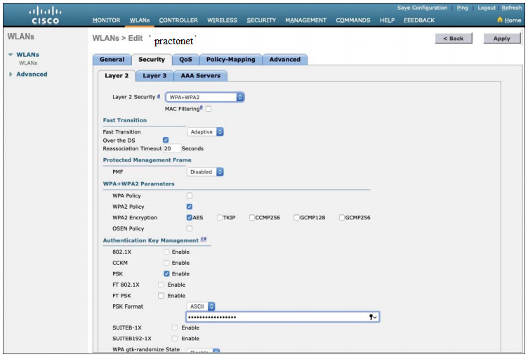
To use WPA2-Enterprise, the 802.1X option would be selected. In that case, 802.1x and EAP would be used to authenticate wireless clients against one or more RADIUS servers. The controller would use servers from the global list you have defined under Security > AAA > RADIUS > Authentication, as described in the “Step 1. Configure a RADIUS Server” section in this chapter. To specify which servers the WLAN should use, you would select the Security tab and then the AAA Servers tab in the WLAN edit screen. You can identify up to six specific RADIUS servers in the WLAN configuration. Beside each server, select a specific server IP address from the drop-down menu of globally defined servers. The servers are tried in sequential order until one of them responds.
By default, a controller will contact a RADIUS server from its management interface. You can override this behavior by checking the box next to Radius Server Overwrite Interface so that the controller sources RADIUS requests from the dynamic interface that is associated with the WLAN.
Configuring WLAN QoS
Select the QoS tab to configure quality of service settings for the WLAN. By default, the controller will consider all frames in the WLAN to be normal data, to be handled in a “best effort” manner. You can set the Quality of Service (QoS) dropdown menu to classify all frames in one of the following ways:
- Platinum (voice)
- Gold (video)
- Silver (best effort)
- Bronze (background)
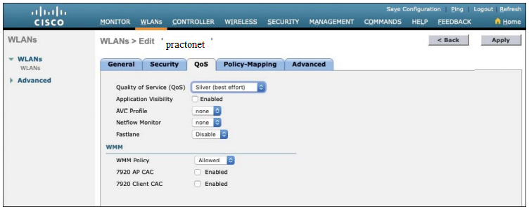
You can also set the Wi-Fi Multimedia (WMM) policy, call admission control (CAC) policies, and bandwidth parameters on the QoS page.
Configuring Advanced WLAN Settings
Finally, you can select the Advanced tab to configure a variety of advanced WLAN settings. From the page you can enable functions such as coverage hole detection, peer-to-peer blocking, client exclusion, client load limits, and so on. By default, client sessions with the WLAN are limited to 1800 seconds (30 minutes). Once that session time expires, a client will be required to reauthenticate. This setting is controlled by the Enable Session Timeout check box and the Timeout field.
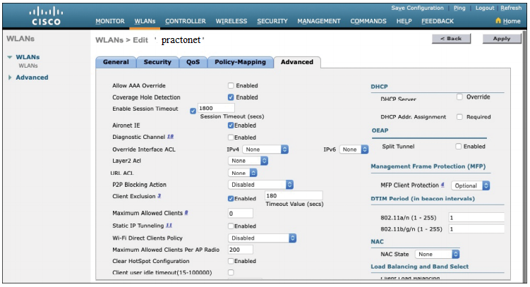
A controller maintains a set of security policies that are used to detect potentially malicious wireless clients. If a client exhibits a certain behavior, the controller can exclude it from the WLAN for a period of time. By default, all clients are subject to the policies configured under Security > Wireless Protection Policies > Client Exclusion Policies. These policies include excessive 802.11 association failures, 802.11 authentication failures, 802.1x authentication failures, web authentication failures, and IP address theft or reuse. Offending clients will be automatically excluded or blocked for 60 seconds, as a deterrent to attacks on the wireless network.
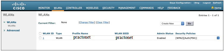
Finalizing WLAN Configuration
When you are satisfied with the settings in each of the WLAN configuration tabs, click the Apply button in the upper-right corner of the WLAN Edit screen. The WLAN will be created and added to the controller configuration. below practonet WLAN has been added as WLAN ID 1 and is enabled for use.
Be aware that, by default, a controller will not allow management traffic that is initiated from a WLAN. That means you (or anybody else) cannot access the controller GUI or CLI from a wireless device that is associated to the WLAN. This is considered to be a good security practice because the controller is kept isolated from networks that might be easily accessible or where someone might eavesdrop on the management session traffic. Instead, you can access the controller through its wired interfaces. You can change the default behavior on a global basis (all WLANs) by selecting the Management tab and then selecting Mgmt Via Wireless. Check the box to allow management sessions from any WLAN that is configured on the controller.