A VLAN is a group of devices on one or more LANs that are configured to communicate as if they were attached to the same wire, when in fact they are located on a number of different LAN segments. Because VLANs are based on logical instead of physical connections, they are extremely flexible.
VLANs define broadcast domains in a Layer 2 network. A broadcast domain is the set of all devices that will receive broadcast frames originating from any device within the set. Broadcast domains are typically bounded by routers because routers do not forward broadcast frames. Layer 2 switches create broadcast domains based on the configuration of the switch. Switches are multiport bridges that allow you to create multiple broadcast domains. Each broadcast domain is like a distinct virtual bridge within a switch.
You can define one or many virtual bridges within a switch. Each virtual bridge you create in the switch defines a new broadcast domain (VLAN). Traffic cannot pass directly to another VLAN (between broadcast domains) within the switch or between two switches. To interconnect two different VLANs, you must use routers or Layer 3 switches.
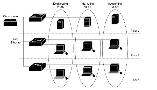
VLANs are often associated with IP subnetworks. For example, all of the end stations in a particular IP subnet belong to the same VLAN. Traffic between VLANs must be routed. You must assign LAN interface VLAN membership on an interface-by-interface basis (this is known as interface-based or static VLAN membership).
VLAN Ranges
With Cisco IOS Release 12.2(25)EW and later, Catalyst 4500 series switches support 4096 VLANs in compliance with the IEEE 802.1Q standard. These VLANs are organized into three ranges: reserved, normal, and extended.
Reserved: Vlan 0, 4095 are reserved, for system use only. You cannot see or use these VLANs.
Normal: Vlan 1 – 1005 are normal vlans. Vlan 1 is Cisco default. You can use this VLAN but you cannot delete it. Vlan 2-1001 are used for Ethernet VLANs; you can create, use, and delete these VLANs. You cannot delete VLANs 1002-1005, Cisco defaults for FDDI and Token Ring.
Extended: Vlan 1006-4094 are for Ethernet VLANs only. When configuring extended-range VLANs, note the following:
•Layer 3 ports and some software features require internal VLANs. Internal VLANs are allocated from 1006 and up. You cannot use a VLAN that has been allocated for such use. To display the VLANs used internally, enter the show vlan internal usage command.
•Switches running Catalyst product family software do not support configuration of VLANs 1006-1024. If you configure VLANs 1006-1024, ensure that the VLANs do not extend to any switches running Catalyst product family software.
•You must enable the extended system ID to use extended range VLANs.
Configuring VLANs
If the switch is in VTP server or transparent mode (see the “Configuring VTP” section), you can configure VLANs in global and VLAN configuration modes. When you configure VLANs in global and config-vlan configuration modes, the VLAN configuration is saved in the vlan.dat files, not the running-config or startup-config files. To display the VLAN configuration, enter the show vlan command.
If the switch is in VLAN transparent mode, use the copy running-config startup-config command to save the VLAN configuration to the startup-config file. After you save the running configuration as the startup configuration, the show running-config and show startup-config commands display the VLAN configuration.
User-configured VLANs have unique IDs from 1 to 4094. To create a VLAN, enter the vlan command with an unused ID. To verify whether a particular ID is in use, enter the show vlan id ID command. To modify a VLAN, enter the vlan command for an existing VLAN.
To create a VLAN, perform this task:Switch# configure terminal
Switch(config)# vlan vlan_ID
Switch(config-vlan)# end
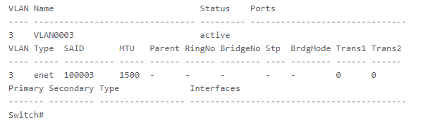
Switch# show vlan [id | name] vlan_name
Example:Switch# configure terminal
Switch(config)# vlan 3
Switch(config-vlan)# end
Switch# show vlan id 3
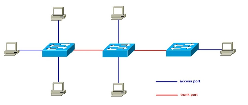
Switch Ports
Each port on a Cisco switch can be configured as either an access or a trunk port. The type of a port specifies how the switch determines the incoming frame’s VLAN. Here is a description of these two port types:
Access port – a port that can be assigned to a single VLAN. The frames that arrive on an access port are assumed to be part of the access VLAN. This port type is configured on switch ports that are connected to devices with a normal network card, for example a host on a network.
Trunk port – a port that is connected to another switch. This port type can carry traffic of multiple VLANs, thus allowing you to extend VLANs across your entire network. Frames are tagged by assigning a VLAN ID to each frame as they traverse between switches.
Understanding Voice VLAN
The voice VLAN feature enables access ports to carry IP voice traffic from an IP phone. When the switch is connected to a Cisco 7960 IP Phone, the phone sends voice traffic with Layer 3 IP precedence and Layer 2 class of service (CoS) values, which are both set to 5 by default. Because the sound quality of an IP phone call can deteriorate if the data is unevenly sent, the switch supports quality of service (QoS) based on IEEE 802.1p CoS. QoS uses classification and scheduling to send network traffic from the switch in a predictable manner.
The Cisco 7960 IP Phone is a configurable device, and you can configure it to forward traffic with an IEEE 802.1p priority. You can configure the switch to trust or override the traffic priority assigned by a Cisco IP Phone. The Cisco IP Phone contains an integrated three-port 10/100 switch. The ports provide dedicated connections to these devices:
•Port 1 connects to the switch or other voice-over-IP (VoIP) device.
•Port 2 is an internal 10/100 interface that carries the IP Phone traffic.
•Port 3 (access port) connects to a PC or other device.
You can configure an access port with an attached Cisco IP Phone to use one VLAN for voice traffic and another VLAN for data traffic from a device attached to the phone. You can configure access ports on the switch to send Cisco Discovery Protocol (CDP) packets that instruct an attached phone to send voice traffic to the switch in any of these ways:
•In the voice VLAN tagged with a Layer 2 CoS priority value
•In the access VLAN tagged with a Layer 2 CoS priority value
•In the access VLAN, untagged (no Layer 2 CoS priority value)
This example shows how to configure a port connected to a Cisco IP Phone to use the CoS value to classify incoming traffic, to use IEEE 802.1p priority tagging for voice traffic, and to use the default native VLAN (VLAN 0) to carry all traffic:
Switch# configure terminal
Enter configuration commands, one per line. End with CNTL/Z.
Switch(config)# interface gigabitethernet0/1
Switch(config-if)# mls qos trust cos
Switch(config-if)# switchport voice vlan dot1p
Switch(config-if)# end
Default Vlan
All switch ports become a member of the default VLAN after the initial boot up of the switch. Having all the switch ports participate in the default VLAN makes them all part of the same broadcast domain. This allows any device connected to any switch port to communicate with other devices on other switch ports. The default VLAN for Cisco switches is VLAN 1.
VLAN 1 has all the features of any VLAN, except that you cannot rename it and you cannot delete it. Layer 2 control traffic, such as CDP and spanning tree protocol traffic, will always be associated with VLAN 1 – this cannot be changed. In the figure, VLAN 1 traffic is forwarded over the VLAN trunks connecting the S1, S2, and S3 switches. It is a security best practice to change the default VLAN to a VLAN other than VLAN 1; this entails configuring all the ports on the switch to be associated with a default VLAN other than VLAN 1. VLAN trunks support the transmission of traffic from more than one VLAN. Although VLAN trunks are mentioned throughout this section, they are explained in the next section on VLAN trunking.