
In modern networks, security must be implemented in depth. The security architecture should use firewalls and intrusion prevention systems (IPS) at strategic locations, and hosts should use antivirus and antimalware tools. Routers, which already need to exist throughout the enterprise at the edge between local-area networks and wide-area networks, can be configured with IP access control lists to filter packets related to different IP address ranges in that enterprise.
LAN switches have a unique opportunity as a security enforcement point, particularly LAN switches connected to endpoint devices. Attackers often launch attacks from the endpoints connected to an enterprise LAN switch. The attacker might gain physical access to the endpoint or first infect the device to then launch an attack. Additionally, a mobile device can become infected while outside the company network and then later connect to the company network, with the attack launching at that point.
Port Security Concepts and Configuration
If the network engineer knows what devices should be cabled and connected to particular interfaces on a switch, the engineer can use port security to restrict that interface so that only the expected devices can use it. This reduces exposure to attacks in which the attacker connects a laptop to some unused switch port. When that inappropriate device attempts to send frames to the switch interface, the switch can take different actions, ranging from simply issuing informational messages to effectively shutting down the interface.
Port security identifies devices based on the source MAC address of Ethernet frames that the devices send. For example, PC1 sends a frame, with PC1’s MAC address as the source address. SW1’s F0/1 interface can be configured with port security, and if so, SW1 would examine PC1’s MAC address and decide whether PC1 was allowed to send frames into port F0/1.
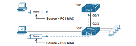
Port security also has no restrictions on whether the frame came from a local device or was forwarded through other switches. For example, switch SW1 could use port security on its G0/1 interface, checking the source MAC address of the frame from PC2, when forwarded up to SW1 from SW2. Port security has several flexible options, but all operate with the same core concepts. First, switches enable port security per port, with different settings available per port. Each port has a maximum number of allowed MAC addresses, meaning that for all frames entering that port, only that number of different source MAC addresses can be used before port security thinks a violation has occurred. When a frame with a new source MAC address arrives, pushing the number of MAC addresses past the allowed maximum, a port security violation occurs. At that point, the switch takes action—by default, discarding all future incoming traffic on that port.
The following list summarizes these ideas common to all variations of port security:
- It examines frames received on the interface to determine if a violation has occurred.
- It defines a maximum number of unique source MAC addresses allowed for all coming in the interface.
- It keeps a list and counter of all unique source MAC addresses on the interface.
- It monitors newly learned MAC addresses, considering those MAC addresses to cause a violation if the newly learned MAC address would push the total number of MAC table entries for the interface past the configured maximum allowed MAC addresses for that port.
- It takes action to discard frames from the violating MAC addresses, plus other actions depending on the configured violation mode.
Those rules define the basics, but port security allows other options as well, including options like these:
- Define a maximum of three MAC addresses, defining all three specific MAC addresses.
- Define a maximum of three MAC addresses but allow those addresses to be dynamically learned, allowing the first three MAC addresses learned.
- Define a maximum of three MAC addresses, predefining one specific MAC address, and allowing two more to be dynamically learned.
Configuring Port Security
Port security configuration involves several steps. First, port security works on both access ports and trunk ports, but it requires you to statically configure the port as a trunk or an access port, rather than let the switch dynamically decide whether to use trunking. The following configuration checklist details how to enable port security, set the maximum allowed MAC addresses per port, and configure the actual MAC addresses:
- Step 1. Use the
switchport mode accessor theswitchport mode trunkinterface subcommands, respectively, to make the switch interface either a static access or trunk interface. - Step 2. Use the
switchport port-securityinterface subcommand to enable port security on the interface. - Step 3. (Optional) Use the
switchport port-security maximumnumber interface subcommand to override the default maximum number of allowed MAC addresses associated with the interface (1). - Step 4. (Optional) Use the
switchport port-security violation {protect | restrict |shutdown}interface subcommand to override the default action to take upon a security violation (shutdown). - Step 5. (Optional) Use the
switchport port-security mac-addressmac-address interface subcommand to predefine any allowed source MAC addresses for this interface. Use the command multiple times to define more than one MAC address. - Step 6. (Optional) Use the
switchport port-security mac-address stickyinterface subcommand to tell the switch to “sticky learn” dynamically learned MAC addresses.
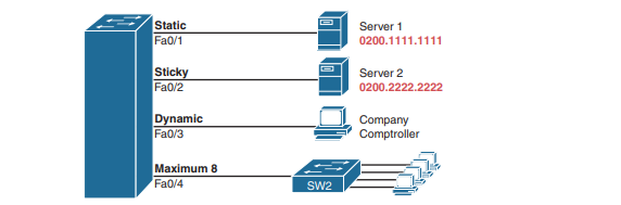
To demonstrate how to configure this variety of the settings, Three ports operate as access ports, while port F0/4, connected to another switch, operates as a trunk.
SW1# show running-config
(Lines omitted for brevity)
interface FastEthernet0/1
switchport mode access
switchport port-security
switchport port-security mac-address 0200.1111.1111
!
interface FastEthernet0/2
switchport mode access
switchport port-security
switchport port-security mac-address sticky
!
interface FastEthernet0/3
switchport mode access
switchport port-security
!
interface FastEthernet0/4
switchport mode trunk
switchport port-security
switchport port-security maximum 8
The switchport port-security command enables port security, with all defaults, with the switchport mode access command meeting the requirement to configure the port as either an access or trunk port. The final port, F0/4, has a similar configuration, except that it has been configured as a trunk rather than as an access port.
The first interface, FastEthernet 0/1, adds one optional port security subcommand: switchport port-security mac-address 0200.1111.1111, which defines a specific source MAC address. With the default maximum source address setting of 1, only frames with source MAC 0200.1111.1111 will be allowed in this port. When a frame with a source other than 0200.1111.1111 enters F0/1, the switch would normally perform MAC address learning and want to add the new source MAC address to the MAC address table. Port security will see that action as learning one too many MAC addresses on the port, taking the default violation action to disable the interface.
As a second example, FastEthernet 0/2 uses the same logic as FastEthernet 0/1, except that it uses the sticky learning feature. For port F0/2, the configuration of the switchport port-security mac-address sticky command tells the switch to dynamically learn source MAC addresses and add port-security commands to the running-config.
Verifying Port Security
The show port-security interface command provides the most insight to how port security operates. This command lists the configuration settings for port security on an interface; plus it lists several important facts about the current operation of port security, including information about any security violations.SW1#show port-security interface fastEthernet 0/2
Port Security : Enabled
Port Status : Secure-up
Violation Mode : Shutdown
Aging Time : 0 mins
Aging Type : Absolute
SecureStatic Address Aging : Disabled
Maximum MAC Addresses : 1
Total MAC Addresses : 1
Configured MAC Addresses : 1
Sticky MAC Addresses : 1
Last Source Address:Vlan : 0200.2222.2222:1
Security Violation Count : 0
Port Security MAC Addresses
Once a switch port has been configured with port security, the switch no longer considers MAC addresses associated with that port as being dynamic entries as listed with the show mac address-table dynamic EXEC command. Even if the MAC addresses are dynamically learned, once port security has been enabled, you need to use one of these options to see the MAC table entries associated with ports using port security:
show mac address-table secure: Lists MAC addresses associated with ports that use port securityshow mac address-table static: Lists MAC addresses associated with ports that use port security, as well as any other statically defined MAC addresses
Below example shows two commands about interface F0/2 from the port security. In that example, port security was configured on F0/2 with sticky learning, so from a literal sense, the switch learned a MAC address off that port (0200.2222.2222). However, the show mac address-table dynamic command does not list the address and port because IOS considers that MAC table entry to be a static entry. The show mac address-table secure command does list the address and port.
SW1# show mac address-table secure interface F0/2
Mac Address Table
-------------------------------------------
Vlan Mac Address Type Ports
---- ----------- -------- -----
1 0200.2222.2222 STATIC Fa0/2
Total Mac Addresses for this criterion: 1
SW1# show mac address-table dynamic interface f0/2
Mac Address Table
-------------------------------------------
Vlan Mac Address Type Ports
---- ----------- -------- -----
SW1#
Port Security Violation Modes
The violation mode defines how port security should react when a violation occurs. Any received frame that breaks the port security rules on an interface is violation.
- For an interface that allows any two MAC addresses, a violation occurs when the total of preconfigured and learned MAC addresses on the interface exceeds the configured maximum of two.
- For an interface that predefines all the specific MAC addresses allowed on the interface, a violation occurs when the switch receives a frame whose source MAC is not one of those configured addresses.
With port security, each switch port can be configured to use one of three violation modes that defines the actions to take when a violation occurs. All three options cause the switch to discard the offending frame (a frame whose source MAC address would push the number of learned MAC addresses over the limit). However, the modes vary in how many other steps they take.below table lists the three modes, their actions, along with the keywords that enable each mode on the switchport port-security violation {protect | restrict | shutdown} interface subcommand.
| Switch port-security Violation | Protect | Restrict | Shutdown |
|---|---|---|---|
| Discards offending traffic | Yes | Yes | Yes |
| Sends log and SNMP messages | Yes | No | Yes |
| Disables the interface by putting it in an err-disabled state, discarding all traffic | No | No | Yes |
Port Security Shutdown Mode
When the (default) shutdown violation mode is used and a port security violation occurs on a port, port security stops all frame forwarding on the interface, both in and out of the port. In effect, it acts as if port security has shut down the port; however, it does not literally configure the port with the shutdown interface subcommand. Instead, port security uses the err-disabled feature. Cisco switches use the err-disabled state for a wide range of purposes, but when using port security shutdown mode and a violation occurs, the following happens:
- The switch interface state (per show interfaces and show interfaces status) changes to an err-disabled state .
- The switch interface port security state (per show port-security) changes to a securedown state.
- The switch stops sending and receiving frames on the interface.
Once port security has placed a port in err-disabled state, by default the port remains in an err-disabled state until someone takes action. To recover from an err-disabled state, the interface must be shut down with the shutdown command and then enabled with the no shutdown command. Alternately, the switch can be configured to automatically recover from the err-disabled state, when caused by port security, with these commands:
errdisable recovery cause psecure-violation: A global command to enable automatic recovery for interfaces in an err-disabled state caused by port securityerrdisable recovery interval seconds: A global command to set the time to wait before recovering the interface
SW1# show port-security
Secure Port MaxSecureAddr CurrentAddr SecurityViolation Security Action
(Count) (Count) (Count)
---------------------------------------------------------------------------
Fa0/13 1 1 1 Shutdown
---------------------------------------------------------------------------
Total Addresses in System (excluding one mac per port) : 0
Max Addresses limit in System (excluding one mac per port) : 8192
Port Security Protect and Restrict Modes
The restrict and protect violation modes take a much different approach to securing ports. These modes still discard offending traffic, but the interface remains in a connected (up/ up) state and in a port security state of secure-up. As a result, the port continues to forward good traffic but discards offending traffic. Having a port in a seemingly good state that also discards traffic can be a challenge when troubleshooting. Basically, you have to know about the feature and then know how to tell when port security is discarding some traffic on a port even though the interface status looks good.
With protect mode, the only action the switch takes for a frame that violates the port security rules is to discard the frame. The switch does not change the port to an err-disabled state, does not generate messages, and does not even increment the violations counter. Below output shows a sample with protect mode after several violations have occurred. Note that the show command confirms the mode (protect) as configured in the top part of the example, with a port security state of secure-up—a state that will not change in protect mode. Also, note that the counter at the bottom shows 0, even though several violations have occurred, because protect mode does not count the violating framesSW1# show running-config
! Lines omitted for brevity
interface FastEthernet0/13
switchport mode access
switchport port-security
switchport port-security mac-address 0200.1111.1111
switchport port-security violation protect
! Lines omitted for brevity
SW1# show port-security interface Fa0/13
Port Security : Enabled
Port Status : Secure-up
Violation Mode : Protect
Aging Time : 0 mins
Aging Type : Absolute
SecureStatic Address Aging : Disabled
Maximum MAC Addresses : 1
Total MAC Addresses : 1
Configured MAC Addresses : 1
Sticky MAC Addresses : 0
Last Source Address:Vlan : 0000.0000.0000:0
Security Violation Count : 0
DHCP Snooping
DHCP Snooping on a switch acts like a firewall or an ACL in many ways. It analyzes incoming messages on the specified subset of ports in a VLAN. DHCP Snooping never filters non-DHCP messages, but it may choose to filter DHCP messages, applying logic to make a choice—allow the incoming DHCP message or discard the message. While DHCP itself provides a Layer 3 service, DHCP Snooping operates on LAN switches and is commonly used on Layer 2 LAN switches and enabled on Layer 2 ports. The reason to put DHCP Snooping on the switch is that the function needs to be performed between a typical end-user device—the type of device that acts as a DHCP client—and DHCP servers or DHCP relay agents.
Let see the sample network that provides a good backdrop to discuss DHCP Snooping. First, all devices connect to Layer 2 switch SW2, with all ports as Layer 2 switchports, all in the same VLAN. The typical DHCP clients sit on the right of the figure. The left shows other devices that could be the path through which to reach a DHCP server.
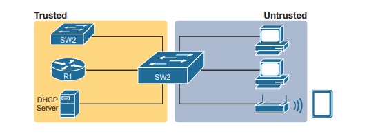
DHCP Snooping works first on all ports in a VLAN, but with each port being trusted or untrusted by DHCP Snooping. To understand why, consider this summary of the general rules used by DHCP Snooping. Note that the rules differentiate between messages normally sent by servers (like DHCPOFFER and DHCPACK) versus those normally sent by DHCP clients:
- DHCP messages received on an untrusted port, for messages normally sent by a server, will always be discarded.
- DHCP messages received on an untrusted port, as normally sent by a DHCP client, may be filtered if they appear to be part of an attack.
- DHCP messages received on a trusted port will be forwarded; trusted ports do not filter (discard) any DHCP messages.
DHCP Snooping Logic
DHCP Snooping defeats dhcp attacks by making most ports untrusted, which by definition would filter the DHCP server messages that arrive on the untrusted ports.
To appreciate the broader set of DHCP Snooping rules and logic, it helps to have a handy reference of some of the more common DHCP messages and processes. For a quick review, the normal message flow includes this sequence: DISCOVER, OFFER, REQUEST, ACK (DORA). In particular:
- Clients send DISCOVER and REQUEST.
- Servers send OFFER and ACK.
Additionally, DHCP clients also use the DHCP RELEASE and DHCP DECLINE messages. When a client has a working lease for an address but no longer wants to use the address, the DHCP client can tell the DHCP server it no longer needs the address, releasing it back to the DHCP server, with the DHCP RELEASE message. Similarly, a client can send a DHCP DECLINE message to turn down the use of an IP address during the normal DORA flow on messages.
Now to the logic for DHCP Snooping untrusted ports. Below figure summarizes the ideas, with two switch ports. On the left, the switch port connects to a DHCP server, so it should be trusted; otherwise DHCP would not work, because the switch would filter all DHCP messages sent by the DHCP server. On the right, PC1 connects to an untrusted port with a DHCP client.
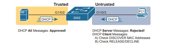
The following list summarizes the DHCP Snooping rules :
- Examine all incoming DHCP messages.
- If normally sent by servers, discard the message.
- If normally sent by clients, filter as follows:
- For DISCOVER and REQUEST messages, check for MAC address consistency between the Ethernet frame and the DHCP message.
- For RELEASE or DECLINE messages, check the incoming interface plus IP address versus the DHCP Snooping binding table.
- For messages not filtered that result in a DHCP lease, build a new entry to the DHCP Snooping binding table.
Filtering DISCOVER Messages Based on MAC Address
DHCP Snooping does one straightforward check for the most common client-sent messages: DISCOVER and REQUEST. First, note that DHCP messages define the chaddr (client hardware address) field to identify the client. Hosts on LANs include the device’s MAC address as part of chaddr. As usual, Ethernet hosts encapsulate the DHCP messages inside Ethernet frames, and those frames of course include a source MAC address—an address that should be the same MAC address used in the DHCP chaddr field. DHCP Snooping does a simple check to make sure those values match.
Figure shows how an attacker could attempt to overload the DHCP server and lease all the addresses in the subnet. The attacker’s PC uses pseudo MAC address A, so all three DISCOVER messages in the figure show a source Ethernet address of “A.” However, each message (in the DHCP data) identifies a different MAC address in the chaddr value, so from a DHCP perspective, each message appears to be a different DHCP request. The attacker can attempt to lease every IP address in the subnet so that no other hosts could obtain a lease.
The core feature of DHCP Snooping defeats this type of attack on untrusted ports. It checks the Ethernet header source MAC address and compares that address to the MAC address in the DHCP header, and if the values do not match, DHCP Snooping discards the message.
Filtering Messages that Release IP Addresses
DHCP Snooping builds the DHCP Snooping binding table for all the DHCP flows it sees that it allows to complete. That is, for any working legitimate DHCP flows, it keeps a list of some of the important facts. Then DHCP Snooping, and other features like Dynamic ARP Inspection, can use the table to make decisions.
As an example, consider Figure, which repeats the same topology as above now with one entry in its DHCP Snooping binding table.
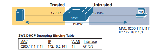
In this simple network, the DHCP client on the right leases IP address 172.16.2.101 from the DHCP server on the left. The switch’s DHCP Snooping feature combines the information from the DHCP messages, with information about the port (interface G1/0/3, assigned to VLAN 11 by the switch), and puts that in the DHCP Snooping binding table. DHCP Snooping then applies additional filtering logic that uses the DHCP Snooping binding table: it checks client-sent messages like RELEASE and DECLINE that would cause the DHCP server to be allowed to release an address. For instance, a legitimate user might lease address 172.16.2.101, and at some point release the address back to the server; however, before the client has finished with its lease, an attacker could send DHCP RELEASE message to release that address back into the pool. The attacker could then immediately try to lease that address, hoping the DHCP server assigns that same 172.16.2.101 address to the attacker.
DHCP Snooping Configuration
DHCP Snooping requires several configuration steps to make it work. First, you need to use a pair of associated global commands: one to enable DHCP Snooping and another to list the VLANs on which to use DHCP Snooping. Both must be included for DHCP Snooping to operate. Second, while not literally required, you will often need to configure a few ports as ports. Most switches that use DHCP Snooping for a VLAN have some trusted ports and some untrusted ports, and with a default of untrusted, you need to configure the trusted ports.
Configuring DHCP Snooping on a Layer 2 Switch
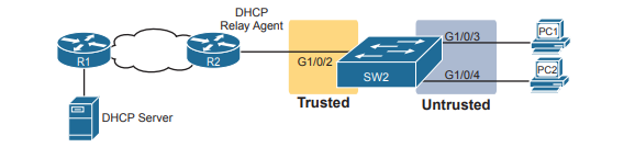
The DHCP server sits on the other side of the WAN, on the left of the figure. As a result, SW2’s port connected to router R2 (a DHCP relay agent) needs to be trusted. On the right, two sample PCs can use the default untrusted setting. Switch SW2 places all the ports in the figure in VLAN 11, so to enable DHCP Snooping in VLAN 11, SW2 requires two commands: ip dhcp snooping and ip dhcp snooping vlan 11. Then, to change the logic on port G1/0/2 (connected to the router) to be trusted, the configuration includes the ip dhcp snooping trust interface subcommand.
ip dhcp snooping
ip dhcp snooping vlan 11
no ip dhcp snooping information option
!
interface GigabitEthernet1/0/2
ip dhcp snooping trust
Above commands is to match figure above DHCP Snooping Configuration.SW2# show ip dhcp snooping
Switch DHCP snooping is enabled
Switch DHCP gleaning is disabled
DHCP snooping is configured on following VLANs:
11
DHCP snooping is operational on following VLANs:
11
Smartlog is configured on following VLANs:
none
Smartlog is operational on following VLANs:
none
DHCP snooping is configured on the following L3 Interfaces:
Insertion of option 82 is disabled
circuit-id default format: vlan-mod-port
remote-id: bcc4.938b.a180 (MAC)
Option 82 on untrusted port is not allowed
Verification of hwaddr field is enabled
Verification of giaddr field is enabled
DHCP snooping trust/rate is configured on the following Interfaces:
Interface Trusted Allow option Rate limit (pps)
----------------------- ------- ------------ ----------------
GigabitEthernet1/0/2 yes yes unlimited
Custom circuit-ids:
The highlighted lines in the example point out a few of the key configuration settings. Starting at the top, the first two confirm the configuration of the ip dhcp snooping and ip dhcp snooping vlan 11 commands , respectively. Also, the highlighted lines at the bottom of the output show a section that lists trusted ports—in this case, only port G1/0/2. Also, you might have noticed that highlighted line in the middle that states Insertion of option 82 is disabled. That line confirms the addition of the no ip dhcp information option command to the configuration. To understand why the example includes this command, consider these facts about DHCP relay agents:
- DHCP relay agents add new fields to DHCP requests—defined as option 82 DHCP header fields (in RFC 3046).
- DHCP Snooping uses default settings that work well if the switch acts as a Layer 3 switch and as a DHCP relay agent, meaning that the switch should insert the DHCP option 82 fields into DHCP messages. In effect, the switch defaults to use
ip dhcp snooping information option. - When the switch does not also act as a DHCP relay agent, the default setting stops DHCP from working for end users. The switch sets fields in the DHCP messages as if it were a DHCP relay agent, but the changes to those messages cause most DHCP servers (and most DHCP relay agents) to ignore the received DHCP messages.
- The conclusion: To make DHCP Snooping work on a switch that is not also a DHCP relay agent, disable the option 82 feature using the
no ip dhcp snooping information optionglobal command.
That concludes the DHCP Snooping configuration that is both required and that you will most often need to make the feature work.
Limiting DHCP Message Rates
Knowing that DHCP Snooping prevents their attacks, what might attackers do in response? Devise new attacks, including attacking DHCP Snooping itself. One way to attack DHCP Snooping takes advantage of the fact that it uses the generalpurpose CPU in a switch. Knowing that, attackers can devise attacks to generate large volumes of DHCP messages in an attempt to overload the DHCP Snooping feature and the switch CPU itself. The goal can be as a simple denial-of-service attack or a combination of attacks that might cause DHCP Snooping to fail to examine every message, allowing other DHCP attacks to then work.
To help prevent this kind of attack, DHCP Snooping includes an optional feature that tracks the number of incoming DHCP messages. If the number of incoming DHCP messages exceeds that limit over a one-second period, DHCP Snooping treats the event as an attack and moves the port to an err-disabled state. Also, the feature can be enabled both on trusted and untrusted interfaces. Although rate limiting DHCP messages can help, placing the port in an err-disabled state can itself create issues. As a reminder, once in the err-disabled state, the switch will not send or receive frames for the interface. However, the err-disabled state might be too severe an action because the default recovery action for an err-disabled state requires the configuration of a shutdown and then a no shutdown subcommand on the interface.
To help strike a better balance, you can enable DHCP Snooping rate limiting and then also configure the switch to automatically recover from the port’s err-disabled state, without the need for a shutdown and then no shutdown command.errdisable recovery cause dhcp-rate-limit
errdisable recovery interval 30
!
interface GigabitEthernet1/0/2
ip dhcp snooping limit rate 10
!
interface GigabitEthernet1/0/3
ip dhcp snooping limit rate 2
A repeat of the show ip dhcp snooping command now shows the rate limits near the end of the output.SW2# show ip dhcp snooping
! Lines omitted for brevity
Interface Trusted Allow option Rate limit (pps)
----------------------- ------- ------------ ----------------
GigabitEthernet1/0/2 yes yes 10
Custom circuit-ids:
GigabitEthernet1/0/3 no no 2
Custom circuit-ids:
DHCP Snooping Configuration Summary
The following configuration checklist summarizes the commands included in this section about how to configure DHCP Snooping.
- Step 1. Configure this pair of commands (both required):
- Use the
ip dhcp snoopingglobal command to enable DHCP Snooping on the switch. - Use the
ip dhcp snooping vlan vlan-listglobal command to identify the VLANs on which to use DHCP Snooping.
- Use the
- Step 2. (Optional): Use the
no ip dhcp snooping information optionglobal command on Layer 2 switches to disable the insertion of DHCP Option 82 data into DHCP messages, specifically on switches that do not act as a DHCP relay agent. - Step 3. Configure the
ip dhcp snooping trustinterface subcommand to override the default setting of not trusted. - Step 4. (Optional): Configure DHCP Snooping rate limits and err-disabled recovery:
- Step A. (Optional): Configure the
ip dhcp snooping limit ratenumber interface subcommand to set a limit of DHCP messages per second. - Step B. (Optional): Configure the
no ip dhcp snooping limit rate numberinterface subcommand to remove an existing limit and reset the interface to use the default of no rate limit. - Step C. (Optional): Configure the
errdisable recovery cause dhcp-rate-limitglobal command to enable the feature of automatic recovery from err-disabled mode, assuming the switch placed the port in err-disabled state because of exceeding DHCP Snooping rate limits. - Step D. (Optional): Configure the
errdisable recovery interval secondsglobal commands to set the time to wait before recovering from an interface err-disabled state (regardless of the cause of the err-disabled).
- Step A. (Optional): Configure the
Dynamic ARP Inspection
The Dynamic ARP Inspection (DAI) feature on a switch examines incoming ARP messages on untrusted ports to filter those it believes to be part of an attack. DAI’s core feature compares incoming ARP messages with two sources of data: the DHCP Snooping binding table and any configured ARP ACLs. If the incoming ARP message does not match the tables in the switch, the switch discards the ARP message.
To understand the attacks DAI can prevent, you need to be ready to compare normal ARP operations with the abnormal use of ARP used in some types of attacks. This uses that same flow, first reviewing a few important ARP details, and then showing how an attacker can just send an ARP reply—called a gratuitous ARP—triggering hosts to add incorrect ARP entries to their ARP tables.
DHCP Snooping Configuration Summary
If all you care about is how ARP works normally, with no concern about attacks, you can think of ARP to the depth shown in Figure. The figure shows a typical sequence. Host PC1 needs to send an IP packet to its default router (R2), so PC1 first sends an ARP request message in an attempt to learn the MAC address associated with R2’s 172.16.2.2 address. Router R2 sends back an ARP reply, listing R2’s MAC address (note the figure shows pseudo MAC addresses to save space).
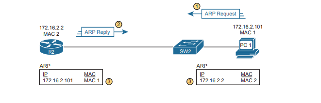
The ARP tables at bottom of the figure imply an important fact: both hosts learn the other host’s MAC address with this two-message flow. Not only does PC1 learn R2’s MAC address based on the ARP reply (message 2), but router R2 learns PC1’s IP and MAC address because of the ARP request (message 1).
The ARP messages define origin IP and hardware (MAC) address fields as well as target IP and hardware address fields. The origin should list the sending device’s IP address and MAC, no matter whether the message is an ARP reply or ARP request. For instance, message 1 in the figure, sent by PC1, lists PC1’s IP and MAC addresses in the origin fields, which is why router R2 could learn that information. PC2 likewise learns of R2’s MAC address per the origin address fields in the ARP reply.
Gratuitous ARP as an Attack Vector
Normally, a host uses ARP when it knows the IP address of another host and wants to learn that host’s MAC address. However, for legitimate reasons, a host might also want to inform all the hosts in the subnet about its MAC address. That might be useful when a host changes its MAC address, for instance. So, ARP supports the idea of a gratuitous ARP message with these features:
- It is an ARP reply.
- It is sent without having first received an ARP request.
- It is sent to an Ethernet destination broadcast address so that all hosts in the subnet receive the message.
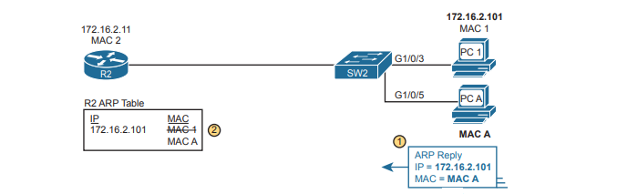
For instance, if a host’s MAC address is MAC A, and it changes to MAC B, to cause all the other hosts to update their ARP tables, the host could send a gratuitous ARP that lists an origin MAC of MAC B. Attackers can take advantage of gratuitous ARPs because they let the sending host make other hosts change their ARP tables. PC A (an attacker) with a gratuitous ARP. However, this ARP lists PC1’s IP address but a different device’s MAC address (PC A) at step 1, causing the router to update its ARP table (step 2).
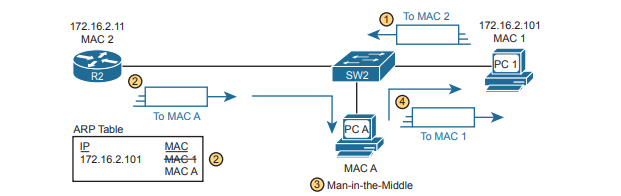
At this point, when R2 forwards IP packets to PC1’s IP address (172.16.2.101), R2 will encapsulate them in an Ethernet frame with PC A as the destination rather than with PC1’s MAC address. At first, this might seem to stop PC1 from working, but instead it could be part of a man-in-the-middle attack so that PC A can copy every message. Figure shows the idea of what happens at this point:
- PC1 sends messages to some server on the left side of router R2.
- The server replies to PC1’s IP address, but R2 forwards that packet to PC A’s MAC address, rather than to PC1.
- PC A copies the packet for later processing.
- PC A forwards the packet inside a new frame to PC1 so that PC1 still works.
Dynamic ARP Inspection Logic
DAI has a variety of features that can prevent these kinds of ARP attacks. To understand how, consider the sequence of a typical client host with regards to both DHCP and ARP. When a host does not have an IP address yet—that is, before the DHCP process completes—it does not need to use ARP. Once the host leases an IP address and learns its subnet mask, it needs ARP to learn the MAC addresses of other hosts or the default router in the subnet, so it sends some ARP messages. In short, DHCP happens first, then ARP. DAI takes an approach for untrusted interfaces that confirms an ARP’s correctness based on DHCP Snooping’s data about the earlier DHCP messages. The correct normal DHCP messages list the IP address leased to a host as well as that host’s MAC address. The DHCP Snooping feature also records those facts into the switch’s DHCP Snooping binding table.
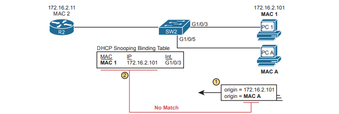
For any DAI untrusted ports, DAI compares the ARP message’s origin IP and origin MAC address fields to the DHCP Snooping binding table. If found in the table, DAI allows the ARP through, but if not, DAI discards the ARP. For instance, below figure shows step 1 in which the attacker at PC A attempts the gratuitous ARP shown earlier. At step 2, DAI makes a comparison to the DHCP Snooping binding table, not finding a match with MAC A along with IP address 172.16.2.101, so DAI would discard the message.
DAI works with the idea of trusted and untrusted ports with the same general rules as DHCP Snooping. Access ports connected to end-user devices are often untrusted by both DHCP Snooping and DAI. Ports connected to other switches, routers, the DHCP server— anything other than links to end-user devices—should be trusted by DAI. Note that although DAI can use the DHCP Snooping table as shown here, it can also use similar statically configured data that lists correct pairs of IP and MAC addresses via a tool called ARP ACLs. Using ARP ACLs with DAI becomes useful for ports connected to devices that use static IP addresses rather than DHCP. Note that DAI looks for both the DCHP Snooping binding data and ARP ACLs.
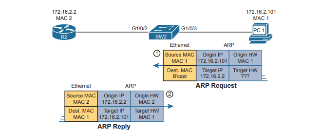
Beyond that core feature, note that DAI can optionally perform other checks as well. For instance, the Ethernet header that encapsulates the ARP should have addresses that match the ARP origin and target MAC addresses. Below shows an example of the comparison of the Ethernet source MAC address and the ARP message origin hardware field.
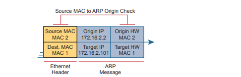
DAI can be enabled to make the comparisons shown in the figure, discarding these messages:
- Messages with an Ethernet header source MAC address that is not equal to the ARP origin hardware (MAC) address
- ARP reply messages with an Ethernet header destination MAC address that is not equal to the ARP target hardware (MAC) address
- Messages with unexpected IP addresses in the two ARP IP address fields
Finally, like DHCP Snooping, DAI does its work in the switch CPU rather than in the switch ASIC, meaning that DAI itself can be more susceptible to DoS attacks. The attacker could generate large numbers of ARP messages, driving up CPU usage in the switch. DAI can avoid these problems through rate limiting the number of ARP messages on a port over time.
Dynamic ARP Inspection Configuration
Configuring DAI requires just a few commands, with the usual larger variety of optional configuration settings. This section examines DAI configuration, first with mostly default settings and with reliance on DHCP Snooping. It then shows a few of the optional features, like rate limits, automatic recovery from err-disabled state, and how to enable additional checks of incoming ARP messages.
Configuring ARP Inspection on a Layer 2 Switch
Before configuring DAI, you need to think about the feature and make a few decisions based on your goals, topology, and device roles. The decisions include the following:
- Choose whether to rely on DHCP Snooping, ARP ACLs, or both.
- If using DHCP Snooping, configure it and make the correct ports trusted for DHCP Snooping .
- Choose the VLAN(s) on which to enable DAI.
- Make DAI trusted (rather than the default setting of untrusted) on select ports in those VLANs, typically for the same ports you trusted for DHCP Snooping.
Just as with DHCP Snooping, switch SW2 on the right should be configured to trust the port connected to the router (G1/0/2), but not trust the two ports connected to the PCs.

ip arp inspection vlan 11
!
interface GigabitEthernet1/0/2
ip arp inspection trust
All ports in the figure connect to VLAN 11, so to enable DAI in VLAN 11, just add the ip arp inspection vlan 11 global command. Then, to change the logic on port G1/0/2 (connected to the router) to be trusted by DAI, add the ip arp inspection trust interface subcommand. This configures DAI, but it omits both DHCP Snooping and ARP ACLs. Below command shows a complete and working DAI configuration that adds the DHCP Snooping configuration to match the DAI configuration above.
ip arp inspection vlan 11
ip dhcp snooping
ip dhcp snooping vlan 11
no ip dhcp snooping information option
!
interface GigabitEthernet1/0/2
ip dhcp snooping trust
ip arp inspection trust
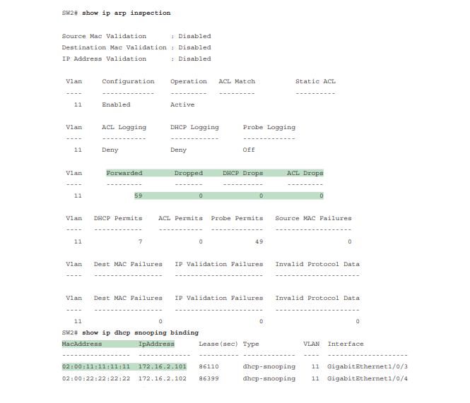
Remember, DHCP occurs first with DHCP clients, and then they send ARP messages. Switch builds its DHCP Snooping binding table by analyzing incoming DHCP messages. Next, any incoming ARP messages on DAI untrusted ports must have matching information in that binding table. show ip arp inspection confirms the key facts about correct DAI operation in this sample network based on the configuration. This gives both configuration settings along with status variables and counters. For instance, the highlighted lines show the total ARP messages received on untrusted ports in that VLAN and the number of dropped ARP messages (currently 0).
Limiting DAI Message Rates
Like DHCP Snooping, DAI can also be the focus of a DoS attack with the attacker generating a large number of ARP messages. Like DHCP Snooping, DAI supports the configuration of rate limits to help prevent those attacks, with a reaction to place the port in an errdisabled state, and with the ability to configure automatic recovery from that err-disabled state. The DHCP Snooping and DAI rate limits do have some small differences in operation, defaults, and in configuration, as follows:
- DAI defaults to use rate limits for all interfaces (trusted and untrusted), with DHCP Snooping defaulting to not use rate limits.
- DAI allows the configuration of a burst interval (a number of seconds), so that the rate limit can have logic like “x ARP messages over y seconds” (DHCP Snooping does not define a burst setting).
It helps to look at DAI and DHCP Snooping rate limit configuration together to make comparisons. The example repeats the exact same DHCP Snooping commands in earlier but but adds the DAI configuration as highlighted.errdisable recovery cause dhcp-rate-limit
errdisable recovery cause arp-inspection
errdisable recovery interval 30
!
interface GigabitEthernet1/0/2
ip dhcp snooping limit rate 10
ip arp inspection limit rate 8
!
interface GigabitEthernet1/0/3
ip dhcp snooping limit rate 2
ip arp inspection limit rate 8 burst interval 4
IP ARP Inspection Configuration Summary
The following configuration checklist summarizes the commands included in this section about how to configure Dynamic IP ARP Inspection:
- Step 1. Use the
ip arp inspection vlan lan-listglobal command to enable Dynamic ARP Inspection (DAI) on the switch for the specified VLANs. - Step 2. Separate from the DAI configuration, also configure DHCP Snooping and/or ARP ACLs for use by DAI.
- Step 3. Configure the
ip arp inspection trustinterface subcommand to override the default setting of not trusted. - Step 4. (Optional): Configure DAI rate limits and err-disabled recovery:
- Step A. (Optional): Configure the
ip arp inspection limit rate number [burst interval seconds]interface subcommand to set a limit of ARP messages per second, or ARP messages for each configured interval. - Step B. (Optional): Configure the
ip arp inspection limit rate noneinterface subcommand to disable rate limits. - Step C. (Optional): Configure the
errdisable recovery cause arp-inspectionglobal command to enable the feature of automatic recovery from err-disabled mode, assuming the switch placed the port in err-disabled state because of exceeding DAI rate limits. - Step D. (Optional): Configure the
errdisable recovery interval secondsglobal commands to set the time to wait before recovering from an interface err-disabled state (regardless of the cause of the err-disabled state).
- Step A. (Optional): Configure the
- Step 5. (Optional): Configure the
ip arp inspection validate {[dst-mac] [src-mac] [ip]}global command to add DAI validation steps.


