Switching is process to forward packets coming in from one port to a port leading towards the destination. When data comes on a port it is called ingress, and when data leaves a port or goes out it is called egress. A communication system may include number of switches and nodes. At broad level, switching can be divided into two major categories:
Connectionless:
The data is forwarded on behalf of forwarding tables. No previous handshaking is required and acknowledgements are optionl.
Connection Oriented:
Before switching data to be forwarded to destination, there is a need to pre-establish circuit along the path between both endpoints. Data is then forwarded on that circuit. After the transfer is completed, circuits can be kept for future use or can be turned down immediately.
A network switch is a multiport network bridge that uses MAC addresses to forward data at the data link layer (layer 2) of the OSI model. Some switches can also forward data at the network layer (layer 3) by additionally incorporating routing functionality. Such switches are commonly known as layer-3 switches or multilayer switches. It forwards frames on the basis of MAC address and it has single broadcast domain an multiple collision domain.

Switch performs:-
- Learning source MAC address
- Forwarding and filtering Layer 2 data
- Loop avoidance
- Switch performs 2 Table CAM/MAC address table and TCAM table
MAC learning and aging
To switch frames between LAN ports efficiently, the switch maintains an address table called the MAC table. When the switch receives a frame, it associates the media access control (MAC) address of the sending network device with the LAN port on which it was received. MAC address learning is enabled on all VLANs by default, The switch dynamically builds the address table by using the MAC source address of the frames received. When the switch receives a frame for a MAC destination address not listed in its address table, it floods the frame to all LAN ports of the same VLAN except the port that received the frame. When the destination station replies, the switch adds its relevant MAC source address and port ID to the address table. The switch then forwards subsequent frames to a single LAN port without flooding all LAN ports. You can also enter a MAC address, which is termed a static MAC address, into the table. These static MAC entries are retained across a reboot of the switch.
MAC Aging: You can configure the amount of time that an entry (the packet source MAC address and port that packet ingresses) remains in the MAC table. You can also configure MAC aging time in interface configuration mode or VLAN configuration mode. The MAC aging time specifies the time before an entry ages out and is discarded from the MAC address table. The range is from 0 to 1000000; the default is 300 seconds. Entering the value 0 disables the MAC aging. If a VLAN is not specified, the aging specification applies to all VLANs.
Static MAC Address: You can configure static MAC addresses on a service instance. Static MAC address configuration on service instances eliminates the need for MAC address learning, which is required for traffic forwarding. Without MAC address learning, MAC address table resources can be conserved and network resources can be optimized. Static MAC address support on service instances provides the following benefits:
• Facilitates optimization of network resources.
• Conserves MAC table resources when used for upstream traffic.
• But Multicast static MAC addresses are not allowed in MAC address configurations.
Static MAC Learning
switch# enableswitch# configure terminal
switch(config)# interface type number [interface TenGigabitEthernet 0/45]
switch(config)# service instance id ethernet [evc-id] [service instance 1 ethernet]
switch(config-if-srv)# mac static address mac-address [mac static address 0000.bbbb.cccc]
exit
Removing a MAC Address:
1. enable
2. configure terminal
3. clear mac-address-table [address mac-address] [interface type number] [bridge-domain bridgedomain-id]
4. exit
Display MAC Address Table
#show mac-address-table address mac-addr
#show mac-address-table bridge-domain bridge-domain-id
#show mac-address-table interface type number
Frame switching
LAN switches are characterized by the forwarding method that they support, such as a store-and-forward switch, cut-through switch, or fragment-free switch. Store-and-forward switches store the entire frame in internal memory and check the frame for errors before forwarding the frame to its destination. Store-and-forward switch operation ensures a high level of error-free network traffic, because bad data frames are discarded rather than forwarded across the network With cut-through switching, the LAN switch copies into its memory only the destination MAC address, which is located in the first 6 bytes of the frame following the preamble. The switch looks up the destination MAC address in its switching table, determines the outgoing interface port, and forwards the frame on to its destination through the designated switch port. A cut-through switch reduces delay because the switch begins to forward the frame as soon as it reads the destination MAC address and determines the outgoing switch port Fragment-free switching works like cut-through switching with the exception that a switch in fragment-free mode stores the first 64 bytes of the frame before forwarding. Fragment-free switching can be viewed as a compromise between store-and-forward switching and cut-through switching. The reason fragment-free switching stores only the first 64 bytes of the frame is that most network errors and collisions occur during the first 64 bytes of a frame.
Frame flooding
Switches determine which port a frame must be sent out to reach its destination. If the address is known, the frame is forwarded only on that port. If the layer 2 MAC address is unknown, the frame is flooded to all ports except the one from which it originated. Flooding is used by a switch at layer-2 to send unknown unicast frames to all other interfaces. If a frame is not destined for a host which receives it, the host will ignore it and not be interrupted. This, too, is limited to a broadcast domain.
MAC address table
A MAC address table, sometimes called a Content Addressable Memory (CAM) table, is used on Ethernet switches to determine where to forward traffic on a LAN. The switch maintains an address table called MAC address table in order to efficiently switch frames between interfaces. When the switch receives a frame, it associates the MAC address of the sending device with the switch port on which it was received. In this way, a switch dynamically builds an address table by using the source MAC address of the frames received.
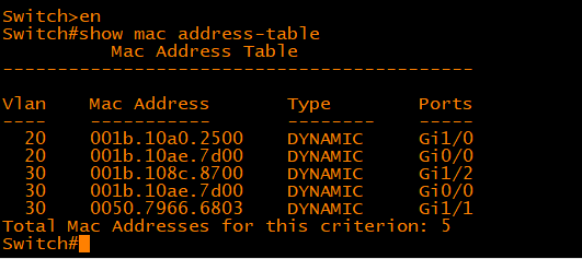
As a practice, try issuing command show mac address-table on Cisco switch CLI. The command show mac address-table, not surprisingly, is used to display the MAC address table of a switch we just talked about, as shown below:

In the above output, you should be able to identify various dynamically learned MAC addresses and the switch ports those MAC addresses are associated with. Each dynamically learned MAC address is associated with one and only one switch port. However, there may be more than one MAC addresses associated with the same switch port which means multiple devices are reachable off the same switch port. There are two possible scenarios in which multiple MAC addresses may be associated with the same switch port. In one case, the switch port may be connected to another switch which in turn has multiple devices connected to it. In the second case, multiple devices may be directly connected to the same switch port through a hub.
Known Unicast:
The switch already has an entry in its MAC address table for the destination MAC address in the frame so it knows exactly which interface leads to the destination of the frame. The switch forwards frame out the single interface associated with the destination MAC address in the frame.

Unknown Unicast:
The switch has no entry in its MAC address table for the destination MAC address in the frame. The switch sends a copy of the frame out all interfaces, other than the interface on which the frame was received. The idea here is that the frame would ultimately reach all hosts and the host having the same MAC address as the destination address of the frame would accept it while all other hosts would reject the frame.
Figure describes how unknown unicasts are propagated in a switched network. Host A yet again sends a frame destined to host B but this time intermediate switches do not yet have an entry for the MAC address of host B in their MAC address tables. Pay careful attention to the direction of arrows and note that the frame sent by host A is received by all hosts in the switched network including hosts connected to other switches. Only host A whose MAC address matches the destination MAC address of the frame would accept that frame while all other devices would reject it. It is not difficult to understand that a lot of bandwidth is wasted here because the frame is sent to every host on the switched network. The negative impact would be more significant in a larger switched network with several switches and possibly hundreds of host.

Broadcast:
The switch sends a copy of the frame out all interfaces, except the interface on which the frame was received, identically to unknown unicasts. This switch behavior is also called frame flooding. Figure describes how broadcasts are propagated in a switched network. Host A sends a broadcast frame with the broadcast destination MAC address of FFFF.FFFF.FFFF and the frame is propagated to all hosts in the network even those connected to other switches.

Multicast:
The switch floods frame identically to unknown unicasts and broadcasts, unless certain multicast optimizations are configured.
There are some problems with the way switches forward different types of frames by default, especially in larger switched networks. First, there is no isolation between hosts and any host can communicate with any other host totally unchecked. This is not a very desirable situation for you as a network administrator as there is no security from malicious software or users. Second, a broadcast sent by any host would reach every other host on the network which is neither bandwidth efficient nor secure. A malfunctioning Network Interface Card (NIC) or a piece of malicious software on a host can generate excessive broadcasts consuming all the bandwidth available and starving legitimate applications. These problems can be greatly alleviated by using virtual LANs or VLANs.


