Routing protocols basically exchange information so routers can learn routes. The routers learn information about subnets, routes to those subnets, and metric information about how good each route is compared to others. The routing protocol can then choose the currently best route to each subnet, building the IP routing table.
Link-state protocols like OSPF take a little different approach to the particulars of what information they exchange and what the routers do with that information once learned. Link-state protocols build IP routes with a couple of major steps. First, the routers together build a lot of information about the network: routers, links, IP addresses, status information, and so on. Then the routers flood the information, so all routers know the same information. At that point, each router can calculate routes to all subnets, but from each router’s own perspective.
Key points to know about OSPF
- Protocol number of OSPF is 89.
- AD value of EIGRP is 110.
- It is default classless.
- Supports CIDR and VLSM.
- Multicast address is 224.0.0.5 & 224.0.0.6
- Has a 2 Timer: Hello (10 sec) and Down(40 sec).
- It supports unlimited hop count.
- It’s metric is cost of link and bandwidth.
- OSPF runs SPF / Dijkstra Algorithm.
- In OSPF Hierarchical model runs, so we must define Area.
- In Hierarchical model, 50-55 router can be given in a single area.
- Maintains 3 tables : Neighbor Table, Database Table & Routing Table
Topology Information and LSAs
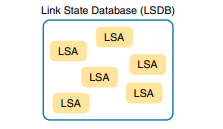
Routers using link-state routing protocols need to collectively advertise practically every detail about the internetwork to all the other routers. At the end of the process of flooding the information to all routers, every router in the internetwork has the exact same information about the internetwork. Flooding a lot of detailed information to every router sounds like a lot of work, and relative to distance vector routing protocols, it is. Open Shortest Path First (OSPF), the most popular link-state IP routing protocol, organizes topology information using LSAs and the link-state database (LSDB). Each LSA is a data structure with some specific information about the network topology; the LSDB is simply the collection of all the LSAs known to a router.
Applying Dijkstra SPF Math to Find the Best Routes
The link-state flooding process results in every router having an identical copy of the LSDB in memory, but the flooding process alone does not cause a router to learn what routes to add to the IP routing table. Although incredibly detailed and useful, the information in the LSDB does not explicitly state each router’s best route to reach a destination. All link-state protocols use a type of math algorithm, called the Dijkstra Shortest Path First (SPF) algorithm, to process the LSDB. That algorithm analyzes the LSDB and builds the routes that the local router should add to the IP routing table—routes that list a subnet number and mask, an outgoing interface, and a next-hop router IP address.
Now that you have the big ideas down, the next several topics walk through the three main phases of how OSPF routers accomplish the work of exchanging LSAs and calculating routes. Those three phases are:
Becoming neighbors: A relationship between two routers that connect to the same data link, created so that the neighboring routers have a means to exchange their LSDBs.
Exchanging databases: The process of sending LSAs to neighbors so that all routers learn the same LSAs.
Adding the best routes: The process of each router independently running SPF, on their local copy of the LSDB, calculating the best routes, and adding those to the IPv4 routing table.
OSPF Neighbourship & Condition
OSPF forms neighbor relationships, called adjacencies, with other routers in the same Area by exchanging Hello packets to multicast address 224.0.0.5. Only after an adjacency is formed can routers share routing information. Each OSPF router is identified by a unique Router ID. The Router ID can be determined in one of three ways:
- The Router ID can be manually specified.
- If not manually specified, the highest IP address configured on any Loopback interface on the router will become the Router ID.
- If no loopback interface exists, the highest IP address configured on any Physical interface will become the Router ID.
By default, Hello packets are sent out OSPF-enabled interfaces every 10 seconds for broadcast and point-to-point interfaces, and 30 seconds for nonbroadcast and point-to-multipoint interfaces. OSPF also has a Dead Interval, which indicates how long a router will wait without hearing any hellos before announcing a neighbor as “down.” Default for the Dead Interval is 40 seconds for broadcast and point-to-point interfaces, and 120 seconds for non-broadcast and point-to-multipoint interfaces. Notice that, by default, the dead interval timer is four times the Hello interval.
OSPF routers will only become neighbors if the following parameters within a Hello packet are identical on each router:
- Area ID must Match
- Hello Deat timer must match
- Authentication must match
- Subnet mask must match
- Must have different router ID
- Must be connected to same VLAN
OSPF Neighbourship Message
- Hello
- DBD
- LSR (Link state request)
- LSU (Link state update)
- LSA (Link state Acknowledgement)
OSPF routers keep track of the status of links within their respective areas. A link is simply a router interface. From these lists of links and their respective statuses, the topology database is created. OSPF routers forward link-state advertisements (LSAs) to ensure the topology database is consistent on each router within an area.
OSPF Neighbourship States
When OSPF routers are initialized, they first start exchanging information using the Hello protocol via the multicast address 224.0.0.5. After the neighbor relationship is established between routers, the routers synchronize their link-state database (LSDB) by reliably exchanging LSAs. They actually exchange quite a bit of vital information when they start up. The relationship that one router has with another consists of eight possible states. All OSPF routers begin the DOWN state, and if all is well, they’ll progress to either the 2WAY or FULL state with their neighbors.
- Down : When no OSPF is running.
- INIT : In this state R1 sends hello but did not received from R2.
- Two Way : Both send and receive hellos. DR and BDR election will occur in this state. DR(Designated router) condition – Highest priority is consider but default is 1 in ospf and if tie highest router id is considered. BDR(Backup Designated router) – second highest router id will become BDR. Neighbourship performed.
- Exstart : Master and slave election will occur in this state. Master will exchange update first and slave will receive and so on.
- Exchange : Master will exchange brief summary description to its remote router.
- Loading : Actual update exchange will perform.
- Full : Adjacency done.
DR/BDR Election
Based on the network type, OSPF router can elect one router to be a Designated Ruter (DR) and one router to be a Backup Designated Router (BDR).For example, on multiaccess broadcast networks (such as LANs) routers defaults to elect a DR and BDR. DR and BDR serve as the central point for exchanging OSPF routing information. Each non-DR or non-BDR router will exchange routing information only with the DR and BDR, instead of exchanging updates with every router on the network segment. DR will then distribute topology information to every other router inside the same area, which greatly reduces OSPF traffic.
To send routing information to a DR or BDR the multicast address of 224.0.0.6 is used. DR sends routing updates to the multicast address of 224.0.0.5. If DR fails, BDR takes over its role of redistributing routing information.Every router on a network segment will establish a full neighbor relationship with the DR and BDR. Non-DR and non-BDR routers will establish a two way neighbor relationship between themselves.
Note: On point-to-point links, a DR and BDR are not elected since only two routers are directly connected.
On LANs, DR and BDR have to be elected. Two rules are used to elect a DR and BDR:
- router with the highest OSPF priority will become a DR. By default, all routers have a priority of 1.
- if there is a tie, a router with the highest router ID wins the election. The router with the second highest OSPF priority or router ID will become a BDR.
To better understand the concept, consider the following example.
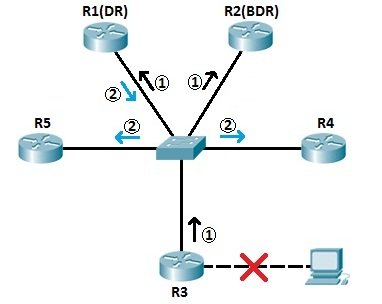
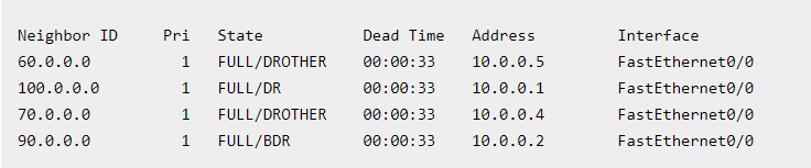
All routers depicted above are in the same area (area 0). All routers are running OSPF. Routers R1 and R2 have been elected as DR and BDR because they have the highest and the second highest router ID (100.0.0.0 and 90.0.0.0 respectively). If, for example, R3’s directly connected subnet fails, R3 informs R1 and R2 (the DR and BDR for the segment) of the network change (step 1). R1 then informs all other non-DR and non-BDR routers of the change in topology (step 2).
We can verify that R1 and R2 are indeed the DR and BDR of the segment by typing the show ip ospf neighbors command on R3:R3#show ip ospf neighbor
NOTE: You can influence the DR and BDR election process by manually configuring the OSPF priority. This is done by using the ip ospf priority "VALUE" command interface command.
Exchanging the LSDB Between Neighbors
Fully Exchanging LSAs with Neighbors
The OSPF neighbor state 2-way means that the router is available to exchange its LSDB with the neighbor. In other words, it is ready to begin a 2-way exchange of the LSDB. So, once two routers on a link reach the 2-way state, they can immediately move on to the process of database exchange. The database exchange process can be quite involved, with several OSPF messages and several interim neighbor states, as above neighborship states described.
After two routers decide to exchange databases, they do not simply send the contents of the entire database. First, they tell each other a list of LSAs in their respective databases—not all the details of the LSAs, just a list. Then each router can check which LSAs it already has and then ask the other router for only the LSAs that are not known yet. The OSPF messages that actually send the LSAs between neighbors are called Link-State Update (LSU) packets. That is, the LSU packet holds data structures called linkstate advertisements (LSA). The LSAs are not packets, but rather data structures that sit inside the LSDB and describe the topology.
Focus on two items in particular:
- The routers exchange the LSAs inside LSU packets.
- When finished, the routers reach a full state, meaning they have fully exchanged the contents of their LSDBs.
Maintaining Neighbors and the LSDB
Once two neighbors reach a full state, they have done all the initial work to exchange OSPF information between them. However, neighbors still have to do some small ongoing tasks to maintain the neighbor relationship. First, routers monitor each neighbor relationship using Hello messages and two related timers: the Hello Interval and the Dead Interval. Routers send Hellos every Hello Interval to each neighbor. Each router expects to receive a Hello from each neighbor based on the Hello Interval, so if a neighbor is silent for the length of the Dead Interval (by default, four times as long as the Hello Interval), the loss of Hellos means that the neighbor has failed.
Next, routers must react when the topology changes as well, and neighbors play a key role in that process. When something changes, one or more routers change one or more LSAs. Then the routers must flood the changed LSAs to each neighbor so that the neighbor can change its LSDB. A third maintenance task done by neighbors is to reflood each LSA occasionally, even when the network is completely stable. By default, each router that creates an LSA also has the responsibility to reflood the LSA every 30 minutes (the default), even if no changes occur.
The following list summarizes these three maintenance tasks for easier review:
- Maintain neighbor state by sending Hello messages based on the Hello Interval and listening for Hellos before the Dead Interval expires
- Flood any changed LSAs to each neighbor
- Reflood unchanged LSAs as their lifetime expires (default 30 minutes)
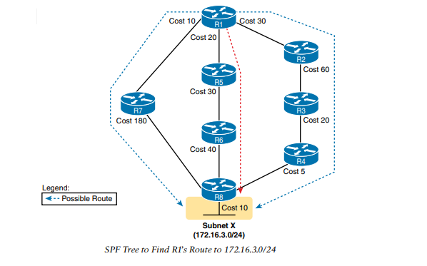
Calculating the Best Routes with SPF
OSPF LSAs contain useful information, but they do not contain the specific information that a router needs to add to its IPv4 routing table. In other words, a router cannot just copy information from the LSDB into a route in the IPv4 routing table. The LSAs individually are more like pieces of a jigsaw puzzle. So, to know what routes to add to the routing table, each router must do some SPF math to choose the best routes from that router’s perspective. The router then adds each route to its routing table: a route with a subnet number and mask, an outgoing interface, and a next-hop router IP address .
The SPF algorithm calculates all the routes for a subnet—that is, all possible routes from the router to the destination subnet. If more than one route exists, the router compares the metrics, picking the best (lowest) metric route to add to the routing table. Although the SPF math can be complex, engineers with a network diagram, router status information, and simple addition can calculate the metric for each route, predicting what SPF will choose.
Once SPF has identified a route, OSPF calculates the metric for a route as follows:
The sum of the OSPF interface costs for all outgoing interfaces in the route. OSPF considers the costs of the outgoing interfaces (only) in each route. It does not add the cost for incoming interfaces in the route.
OSPF Areas and LSAs
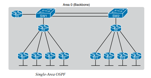
OSPF can be used in some networks with very little thought about design issues. You just turn on OSPF in all the routers, put all interfaces into the same area (usually area 0), and it works! one such network example, with 11 routers and all interfaces in area 0.
Larger OSPFv2 networks suffer with a single-area design. For instance, now imagine an enterprise network with 1000 routers, rather than only 11, and several thousand subnets. As it turns out, the CPU time to run the SPF algorithm on all that topology data just takes time. As a result, OSPFv2 convergence time—the time required to react to changes in the network—can be slow. The routers might run low on RAM as well. Additional problems with a single area design include the following:
- A larger topology database requires more memory on each router.
- The SPF algorithm requires processing power that grows exponentially compared to the size of the topology database.
- A single interface status change anywhere in the internetwork (up to down, or down to up) forces every router to run SPF again.
The solution is to take the one large LSDB and break it into several smaller LSDBs by using OSPF areas. With areas, each link is placed into one area. SPF does its complicated math on the topology inside the area, and that area’s topology only.
OSPF Areas
OSPF area design follows a couple of basic rules. To apply the rules, start with a clean drawing of the internetwork, with routers, and all interfaces. Then choose the area for each router interface, as follows:
- Put all interfaces connected to the same subnet inside the same area.
- An area should be contiguous.
- Some routers may be internal to an area, with all interfaces assigned to that single area.
- Some routers may be Area Border Routers (ABR) because some interfaces connect to the backbone area, and some connect to nonbackbone areas.
- All nonbackbone areas must have a path to reach the backbone area (area 0) by having at least one ABR connected to both the backbone area and the nonbackbone area.
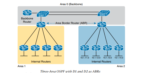
OSPF Design Terminology
- Area Border Router(ABR): An OSPF router with interfaces connected to the backbone area and to at least one other area.
- Backbone router: A router connected to the backbone area (includes ABRs)
- Internal router: A router in one area (not the backbone area)
- Area: A set of routers and links that shares the same detailed LSDB information, but not with routers in other areas, for better efficiency.
- Backbone area: A special OSPF area to which all other areas must connect—area 0
- Intra-area route: A route to a subnet inside the same area as the router
- Interarea route: A route to a subnet in an area of which the router is not a part
Link-State Advertisements (LSAs)
- Router LSA (Type 1) – Contains a list of all links local to the router, and the status and “cost” of those links. Type 1 LSAs are generated by all routers in OSPF, and are flooded to all other routers within the local area.
- Network LSA (Type 2) – Generated by all Designated Routers in OSPF, and contains a list of all routers attached to the Designated Router.
- Network Summary LSA (Type 3) – Generated by all ABRs in OSPF, and contains a list of all destination networks within an area. Type 3 LSAs are sent between areas to allow inter-area communication to occur.
- ASBR Summary LSA (Type 4) – Generated by ABRs in OSPF, and contains a route to any ASBRs in the OSPF system. Type 4 LSAs are sent from an ABR into its local area, so that Internal routers know how to exit the Autonomous System.
- External LSA (Type 5) – Generated by ASBRs in OSPF, and contain routes to destination networks outside the local Autonomous System. Type 5 LSAs can also take the form of a default route to all networks outside the local AS. Type 5 LSAs are flooded to all areas in the OSPF system.
OSPF Configuration – Single Area
Router#config t
Router#router ospf 10 (Note: 10 is process id and is used to distinguish networks)
Router#network 192.168.1.0 0.0.0.255 area 1 (here 192.168.1.0 is network id and 0.0.0.255 is Wildcard mask & area 1 defines that the network lies within which area and must be same to form neighbourship)
Router#^z
[Note:] Simply if you are confuse about subnetmask and wildcard mask then you can remember that Wildcard mask is opposite of subnet mask. If you have network 192.68.5.0 with subnet mask 255.255.0.0 and you want to know wildcard mask then: subract 255.255.0.0 from 255.255.255.255 and resulted is Wildcard mask.
Timers can be adjusted on a per interface basis:Router(config-if)# ip ospf hello-interval 15
Router(config-if)# ip ospf dead-interval 60
Configuring Loopback InterfacesRouter(config)#int loopback 0The IP scheme really doesn’t matter here, but each one being in a separate subnet does. By using the /32 mask, we can use any IP address we want as long as the addresses are never the same on any two routers.
Router(config-if)#ip address 172.31.1.1 255.255.255.255
Verifying OSPF Configuration
There are several ways to verify proper OSPF configuration and operation.
show ip ospf Command: The show ip ospf command is what you’ll need to display OSPF information for one or all OSPF processes running on the router. Information contained therein includes the router ID, area information, SPF statistics, and LSA timer information.
show ip ospf database Command: Show ip ospf database command will give you information about the number of routers in the internetwork (AS) plus the neighboring router’s ID—the topology database I mentioned earlier. Unlike the show ip eigrp topology command, this command reveals the OSPF routers, but not each and every link in the AS like EIGRP does.
show ip ospf interface Command: The show ip ospf interface command reveals all interface-related OSPF information. Data is displayed about OSPF information for all OSPF-enabled interfaces or for specified interfaces.
show ip ospf neighbor Command: The show ip ospf neighbor command is super-useful because it summarizes the pertinent OSPF information regarding neighbors and the adjacency state. If a DR or BDR exists, that information will also be displayed.
show ip protocols Command: The show ip protocols command is also highly useful, whether you’re running OSPF, EIGRP, RIP, BGP or any other routing protocol that can be configured on your router.